MP1567 データシートの表示(PDF) - Monolithic Power Systems
部品番号
コンポーネント説明
メーカー
MP1567 Datasheet PDF : 11 Pages
| |||
TM
MP1567 – 1.2A SYNCHRONOUS RECTIFIED STEP-DOWN CONVERTER
75KHz or lower to insure stable operation.
Lower crossover frequencies result in slower
response and worse transient load recovery.
Higher crossover frequencies degrade the
phase and/or gain margins and can result in
instability.
Choosing the Compensation Components
The values of the compensation components
given in Table 1 yield a stable control loop for
the output voltage and capacitor given.
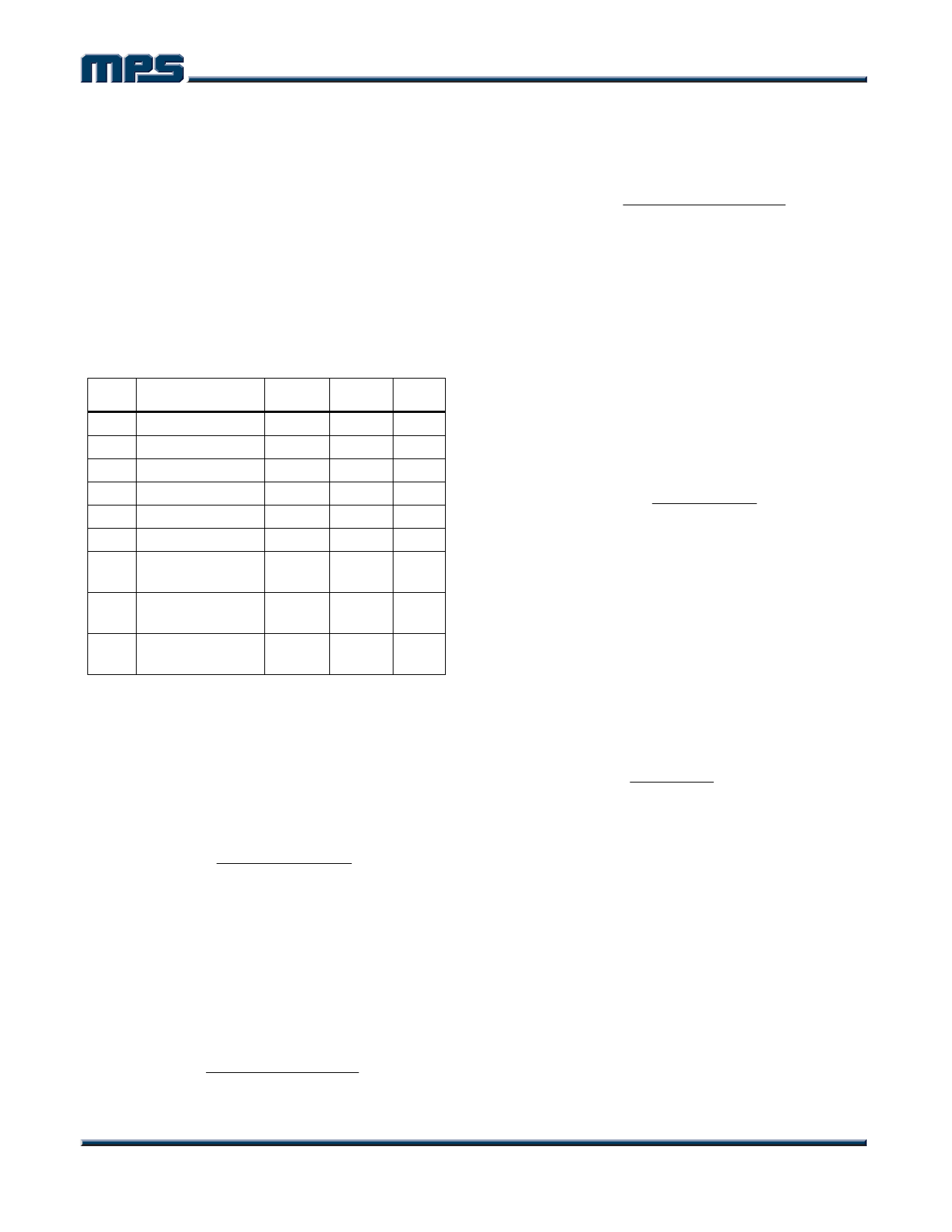
Table 1—Compensation Values for Typical
Output Voltage/Capacitor Combinations
VOUT
1.8V
2.5V
3.3V
1.8V
2.5V
3.3V
1.8V
2.5V
3.3V
C2
4.7µF Ceramic
4.7µF Ceramic
4.7µF Ceramic
10µF Ceramic
10µF Ceramic
10µF Ceramic
47µF Tantalum
(300mΩ)
47µF Tantalum
(300mΩ)
47µF Tantalum
(300mΩ)
R3
3.3kΩ
5.1kΩ
6.8kΩ
7.5kΩ
10kΩ
10kΩ
10kΩ
10kΩ
10kΩ
C3 C4
2.2nF
1.5nF
1.2nF
1nF
820pF
820pF
None
None
None
None
None
None
2.2nF 1.5nF
3.3nF 1.5nF
4.7nF 1.5nF
To optimize the compensation components for
conditions not listed in Table 1, use the
following procedure.
Choose the compensation resistor to set the
desired crossover frequency. Determine the
value by the following equation:
R3 = 2π × C2 × VOUT × fC
GEA × GCS × VFB
Putting in the known constants and setting the
crossover frequency to the desired 75KHz:
R3 ≈ 4.36 × 10⁸ × C2 × VOUT
In this case, the actual crossover frequency is
less than the desired 75KHz, and it is
calculated by:
fC
=
R3 × GEA × GCS × VFB
2π × C2 × VOUT
Choose the compensation capacitor to set the
zero to one fourth of the crossover frequency.
Determine the value by the following equation:
C3 =
4 × C2 × VOUT
R32 × GEA × GCS × VFB
Determine if the second compensation
capacitor, C4, is required. It is required if the
ESR zero of the output capacitor occurs at less
than four times the crossover frequency, or:
8π × C2 × RESR × fC ≥ 1
Where RESR is the equivalent series resistance
of the output capacitor.
If this is the case, then add the second
compensation capacitor. Determine the value
by the equation:
C4 = C2 × RESR(MAX)
R3
Where RESR(MAX) is the maximum ESR of the
output capacitor.
For Example:
Given:
VOUT = 1.8V
C2 = 10µF Ceramic (ESR = 10mΩ max.)
Calculate:
R3 ≈ 4.36 × 10 8 (10µF) × (1.8V) = 7.85kΩ
(Use the nearest standard value of 7.5kΩ.)
C3 = 1.9 × 10 −14 = 1.05nF
10µF × 1.8V
(Use 1nF since it is a standard value.)
8π × C2 × RESR × fC = 0.19
which is less than 1, therefore the second
compensation capacitor (C4) is not required.
MP1567 Rev. 2.3
www.MonolithicPower.com
8
1/3/2006
MPS Proprietary Information. Unauthorized Photocopy and Duplication Prohibited.
© 2006 MPS. All Rights Reserved.
Share Link: 