MRF1002 データシートの表示(PDF) - Motorola => Freescale
部品番号
コンポーネント説明
メーカー
MRF1002 Datasheet PDF : 6 Pages
| |||
MOTOROLA
SEMICONDUCTOR TECHNICAL DATA
Order this document
by MRF1002MA/D
The RF Line
Microwave Pulse
Power Transistors
. . . designed for Class B and C common base amplifier applications in short
and long pulse TACAN, IFF, DME, and radar transmitters.
• Guaranteed Performance @ 1090 MHz, 35 Vdc
Output Power = 2.0 Watts Peak
Minimum Gain = 10 dB
• 100% Tested for Load Mismatch at All Phase Angles with 10:1 VSWR
• Industry Standard Package
• Nitride Passivated
• Gold Metallized, Emitter Ballasted for Long Life and Resistance to Metal
Migration
• Internal Input Matching for Broadband Operation
• Circuit board photomaster available upon request by contacting
RF Tactical Marketing in Phoenix, AZ.
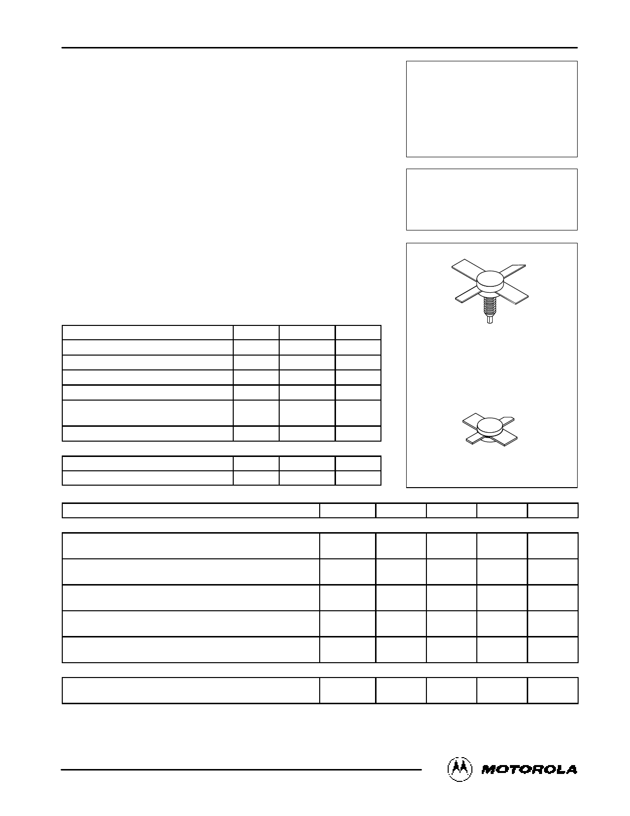
MRF1002MA
MRF1002MB
2.0 W (PEAK), 960 – 1215 MHz
MICROWAVE POWER
TRANSISTORS
NPN SILICON
MAXIMUM RATINGS
Rating
Collector–Emitter Voltage
Collector–Base Voltage
Emitter–Base Voltage
Collector Current — Continuous
Total Device Dissipation @ TC = 25°C (1)
Derate above 25°C
Symbol
VCEO
VCBO
VEBO
IC
PD
Value
20
50
3.5
250
7.0
40
Unit
Vdc
Vdc
Vdc
mAdc
Watts
mW/°C
CASE 332–04, STYLE 1
MRF1002MA
Storage Temperature Range
Tstg
– 65 to +150
°C
THERMAL CHARACTERISTICS
Characteristic
Symbol
Max
Unit
Thermal Resistance, Junction to Case (2)
RθJC
25
°C/W
ELECTRICAL CHARACTERISTICS (TC = 25°C unless otherwise noted.)
Characteristic
Symbol
Min
CASE 332A–03, STYLE 1
MRF1002MB
Typ
Max
Unit
OFF CHARACTERISTICS
Collector–Emitter Breakdown Voltage
(IC = 5.0 mAdc, IB = 0)
Collector–Emitter Breakdown Voltage
(IC = 5.0 mAdc, VBE = 0)
Collector–Base Breakdown Voltage
(IC = 5.0 mAdc, IE = 0)
Emitter–Base Breakdown Voltage
(IE = 1.0 mAdc, IC = 0)
Collector Cutoff Current
(VCB = 35 Vdc, IE = 0)
ON CHARACTERISTICS
V(BR)CEO
20
—
—
Vdc
V(BR)CES
50
—
—
Vdc
V(BR)CBO
50
—
—
Vdc
V(BR)EBO
3.5
—
—
Vdc
ICBO
—
—
0.5
mAdc
DC Current Gain
(IC = 100 mAdc, VCE = 5.0 Vdc)
hFE
10
—
100
—
NOTES:
(continued)
1. These devices are designed for RF operation. The total device dissipation rating applies only when the device is operated as RF amplifiers.
2. Thermal Resistance is determined under specified RF operating conditions by infrared measurement techniques.
REV 6
©MMOotoTrOolaR, OIncL.A19R94F DEVICE DATA
MRF1002MA MRF1002MB
1
Share Link: 