NE5210 データシートの表示(PDF) - Philips Electronics
部品番号
コンポーネント説明
メーカー
NE5210 Datasheet PDF : 14 Pages
| |||
Philips Semiconductors
Transimpedance amplifier (280MHz)
Product specification
NE5210
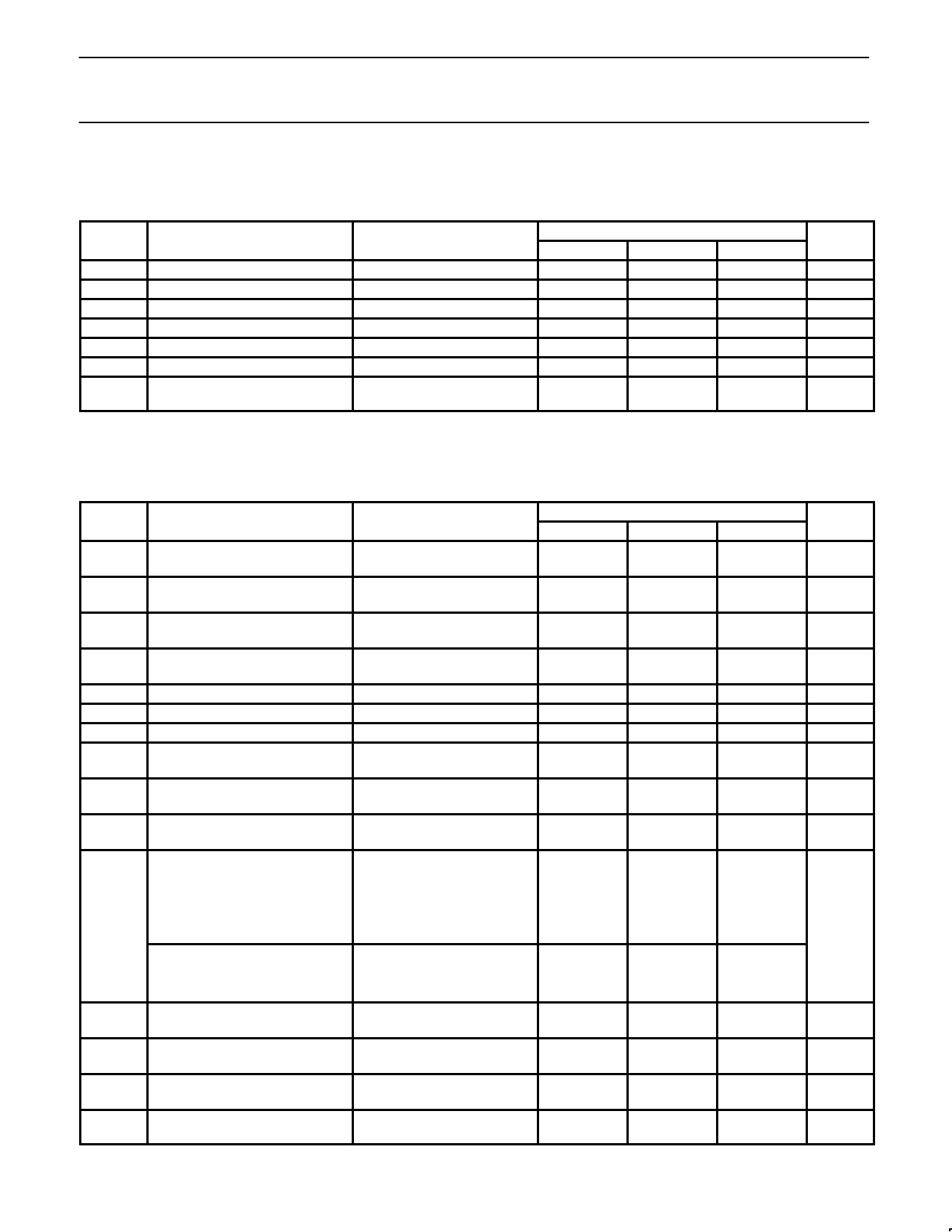
DC ELECTRICAL CHARACTERISTICS
Min and Max limits apply over operating temperature range at VCC=5V, unless otherwise specified. Typical data applies at VCC=5V and
TA=25°C.
SYMBOL
PARAMETER
TEST CONDITIONS
LIMITS
UNIT
Min
Typ
Max
VIN
VO±
VOS
ICC
IOMAX
IIN
IINMAX
Input bias voltage
Output bias voltage
Output offset voltage
Supply current
Output sink/source current1
Input current (2% linearity)
Maximum input current
overload threshold
Test Circuit 8, Procedure 2
Test Circuit 8, Procedure 4
0.6
2.8
21
3
±120
±160
0.8
3.3
0
26
4
±160
±240
0.95
V
3.7
V
80
mV
32
mA
mA
µA
µA
NOTES:
1. Test condition: output quiescent voltage variation is less than 100mV for 3mA load current.
AC ELECTRICAL CHARACTERISTICS
Typical data and Min/Max limits apply at VCC=5V and TA=25°C.
SYMBOL
PARAMETER
TEST CONDITIONS
Min
RT
Transresistance
(differential output)
DC tested, RL=∞
Test Circuit 8, Procedure 1
4.9
RO
Output resistance
(differential output)
DC tested
16
RT
Transresistance
(single-ended output)
DC tested, RL=∞
2.45
RO
Output resistance
(single-ended output)
DC tested
8
f3dB
RIN
CIN
∆R/∆V
Bandwidth (-3dB)
Input resistance
Input capacitance
Transresistance power
supply sensitivity
Test Circuit 1, TA=25°C
200
VCC=5±0.5V
∆R/∆T
Transresistance ambient
temperature sensitivity
∆TA=TA MAX-TA MIN
IN
RMS noise current spectral density
(referred to input)
f=10MHz, TA=25°C
Test Circuit 2
Integrated RMS noise current over
the bandwidth (referred to input)
CS=01
IT
TA=25°C
Test Circuit 2
∆f=100MHz
∆f=200MHz
∆f=300MHz
∆f=100MHz
CS=1pF
∆f=200MHz
∆f=300MHz
PSRR
Power supply rejection ratio2
(VCC1=VCC2)
DC tested, ∆VCC=0.1V
Equivalent AC test circuit 3
20
PSRR
Power supply rejection ratio2
(VCC1)
DC tested, ∆VCC=0.1V
Equivalent AC test circuit 4
20
PSRR
Power supply rejection ratio2
(VCC2)
DC tested, ∆VCC=0.1V
Equivalent AC test circuit 5
PSRR
Power supply rejection ratio2 (ECL
configuration)
f=0.1MHz, Test Circuit 6
LIMITS
Typ
7
30
3.5
15
280
60
7.5
9.6
0.05
3.5
37
56
71
40
66
89
36
36
65
23
UNIT
Max
10
kΩ
42
Ω
5
kΩ
21
Ω
MHz
Ω
pF
20
%/V
0.1
%/°C
6
pA/√Hz
nA
dB
dB
dB
dB
1995 Apr 26
2
Share Link: 