NJM2640 データシートの表示(PDF) - Japan Radio Corporation
部品番号
コンポーネント説明
メーカー
NJM2640 Datasheet PDF : 7 Pages
| |||
NJM2640
3. Design of hall element bias resistance (R1 and R2)
Hall amplifier is a differential amplifier with hysteresis characteristics (24mV typical).
The common-mode input voltage is between 1.5V and Vcc-2V and the input signal must be within the
range.
Non-excitation hall bias voltage is to be set at a half of VCC for effective use of common-mode input
voltage range. Therefore the same value of hall bias resistors is selected for R1 and R2.
Given that the bias current is set to be 5mA by HW101A datasheet, R1 and R2 can be determined as
follows:
R1 + R2 =
Vcc
Ihbias
=
48
5 ×10 −3
= 9.6kΩ
R1 = R2 = 4.8kΩ
The output voltage of hall elements is influenced by the bias current and magnetic flux density of hall
elements.
The optimum input voltage of NJM2640 is 100mVp-p and higher. With such input voltage, the highest
efficiency can be obtained.
4. Design of Power Transistor base resistance (R4 and R5)
HFE of 2SD0968A (NEC) is 50 from its datasheet. Given that Io is 300mA, the base current of TR1 is
6mA.
R4 is given by:
R4 = VCC − VBE − VCE
IB
R4
=
48 − 0.7 −1.5
6 ×10−3
=
7.63 ×103
=
7.6kΩ
Where; VCC is 48V, VCE of NJM2640 is 1.5V, VBE of TR1 is 0.7V
The pull down resistance R5 (connected to TR1) influences turn-off time of TR1.
Faster Turn-off time of TR1 reduces peak current of motor wining current resulting in lower echo fan
noise (often called as Echo noise) during operation.
A typical R5 value is ranging from 1kΩ to 10kΩ. As explained the above, it is highly recommended to
determine the value with actual application for better noise performance.
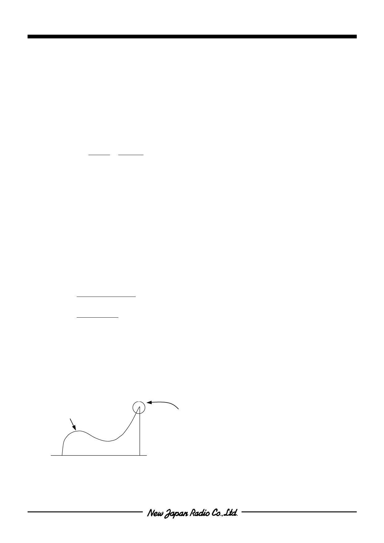
Motor Winding Current
Peak current becomes small early the turnoff the TR1
5. Design of spike killer for power transistor (ZD1 and ZD2)
Zenner diodes (often referred as spike killer ) are used for limiting kick back voltage of motor winding
generated when power transistors is (TR1 and TR2) turned off from on.
-6-
Share Link: 