NL6448BC33-54 データシートの表示(PDF) - NEC => Renesas Technology
部品番号
コンポーネント説明
メーカー
NL6448BC33-54 Datasheet PDF : 28 Pages
| |||
NL6448BC33-54
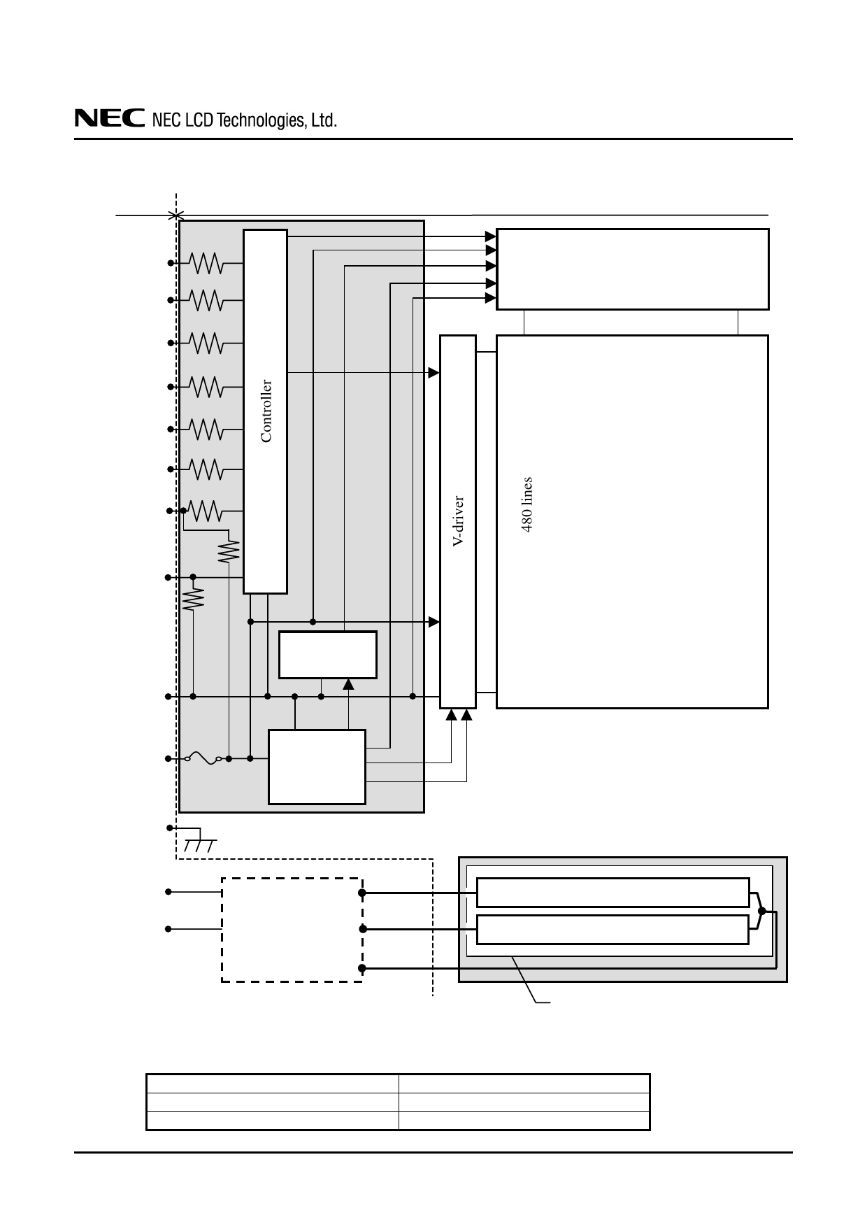
3. BLOCK DIAGRAM
Host
LCD module (Product)
R0 to R5
G0 to G5
B0 to B5
100Ω
100Ω
100Ω
CLK
Hsync
100Ω
100Ω
100Ω
Vsync
100Ω
DE
47kΩ
DPS
8.2kΩ
GND
Note1
Note2
VCC
Fuse
Power supply
for gradation
DC/DC
converter
H-driver
1,920 lines
LCD panel
H: 640 × 3 (R,G,B)
V: 480
FG
Note1
Note2
VDDB
GNDB
Note1
Note2
LCD panel signal processing board
VBLH
Backlight inverter
(Option)
VBLH
VBLC
Note1
Backlight (Edge light type)
Lamp
Lamp
Metallic frame of lamp holder
Note1: Connections between GND (Signal ground), FG (Frame ground) and VBLC (Lamp low voltage
terminal) in the LCD module
GND - FG
GND - VBLC
FG - VBLC
Not connected
Not connected
Not connected
Note2: These grounds should be connected together in customer equipment.
DATA SHEET DOD-PD-0072 (2nd edition)
6
Share Link: 