MH88400-1 データシートの表示(PDF) - Mitel Networks
部品番号
コンポーネント説明
メーカー
MH88400-1 Datasheet PDF : 10 Pages
| |||
Preliminary Information
MH88400
TIP
RING
D1
Meter
Pulse
Detector
14
13
R1
1K 11
C2
10
9
MH88400
6
TIP
VX
RLS
TF
7
VR
TXIN
4
RVLC
RING
VDD
1
LC
AGND
3
2
+
C1
R3 1K
C5
22nF
C3
0.1µF
R4
L1
4.7mH
Audio Output
Audio Input
Ring Voltage & Loop
Current Detect Output
Loop Control Input
+5V
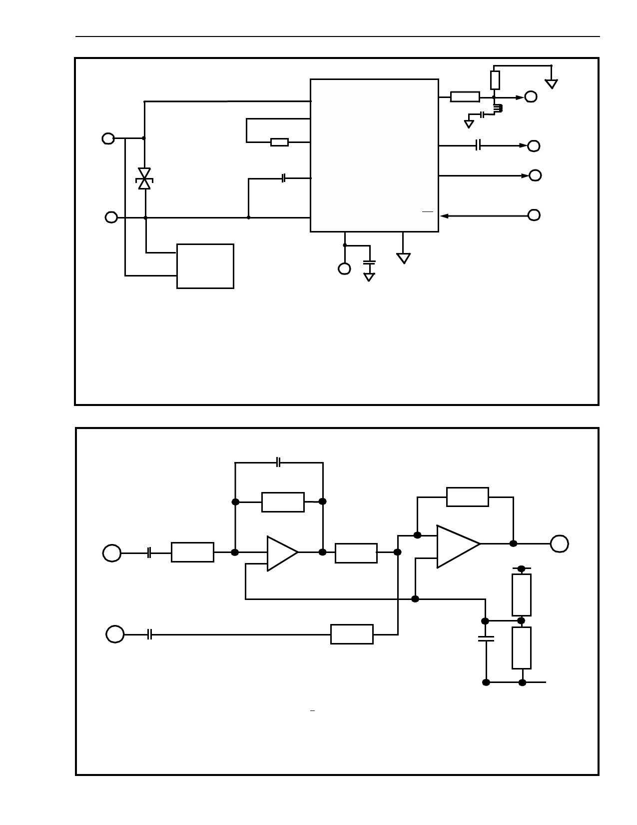
Note:
Meter pulses at high frequency (16kHz or 12kHz) and high
level (10V RMS) are used in some countries. The VX
amplifier has a low pass filter which attenuates by typically
15dB at 16kHz. If this proves insufficient for specific applications,
an LC notch is recommended. This should provide
a further 20dB of rejection at 16 of 12kHz with only 0.5dB of loss
at 3.4kHz (after allowing for the overall 6dB loss caused
by R3, R4).
1) R1: 39Ω,1/2W,5%, current
limiting resistor for use in Germany.
2) C1: 10µF, 6V Tantalum
3) C2: 0.1µF, 250V
4) D1: 180VDC Foldback Diode,
e.g. TISP4180, TISP5180.
5) L1: 4.7mH 5%, eg, Siemens B78108-S
6) C5: 22nF 5% for 16kHz 39nF for 12kHz
Figure 6 - Typical Application Circuit with Meter Pulse Filter and Coupling Capacitors
560pF
5%
68k
100k
1%
From
VR
68k
1%
10nF
5%
1%
62k
1%
- A1
+
-
A1
+
From
VX
100nF
100k
1%
Note:
Amplifier A1 provides a frequency equivalent to the VX path in the MH88400. This
provides the correct phase/amplitude response to enable cancellation to take place in
amplifier A2. Typical THL figures of 15-20dB can be achieved with the values and tolerances
shown. The VR input should be driven from a low impedance < 600R.
This circuit will function correctly for all variants provided the termination impedance of the
external line at the 2W connection is equal to the characteristics impedance of the MH88400.
If it is desired to operate with impedances different from the MH88400 impedances, the
frequency compensation networks around A1 must be filtered. Because of the wide variety
of impedances which are in typical use it is not possible to specify the required values.
10pF
Figure 7 -Transhybrid Loss (THL) Cancellation Circuit
VX Out
100k
100k
0V
2-19
Share Link: 