NTE7057 データシートの表示(PDF) - NTE Electronics
部品番号
コンポーネント説明
メーカー
NTE7057 Datasheet PDF : 3 Pages
| |||
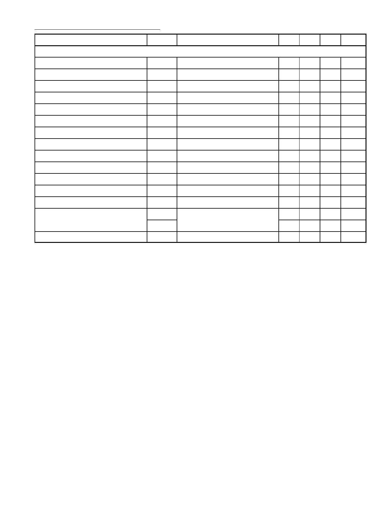
Electrical Characteristics (Cont’d): (TA = +25°C, VCC = 9V unless otherwise specified)
Parameter
Symbol
Test Conditions
Min Typ Max Unit
AC Stage
Input Sensitivity
Maximum IF Input Voltage
IF AGC Range
VINmin Note 1
VINmax
ΔA Note 2
− 75 180 μVrms
74 −
− mVrms
50 60 − dB
Differential Gain
DG Note 3
− − 10 %
Differential Phase
DP Note 3
− − 5 deg.
Video DC Voltage
Sync. Tip Level
Video Output Level
White Noise Threshold
White Noise Clamp Level
Carrier Suppression
V12
VSYNC
VOUT
VWHT
VWCL
CL
Note 4
Note 5
Note 6
Note 7
Note 7
Note 8
4.0 4.5 5.0 V
2.15 2.35 2.55 V
1.45 − 2.05 V
− 5.2 −
V
− 3.5 −
V
40 − − dB
2nd Harm. Suppression
I 2nd Note 9
40 − − dB
AFT Sensitivity
ΔF/ΔV Note 10
− − 37 kHz/V
AFT Output
920kHz Beat
Lower VU
Upper VL
I920 Note 11
0 − 0.3 V
8.0 − 9.0 V
30 38 − dB
Note 1. PIF IN: f = 58.75MHz, fm = 1kHz, 30% AM Modulation.
Adjust PIF input level so that the detected output of P12 with high impedance probe will be
6VP−P and measure the input level.
Note 2. Measure PIF Input Level V1, V2 same as Note 1.
Apply P7 = 9V at V1
Apply P7 = 3V at V2
ΔA = 20log (V1/V2) (dB)
Note 3. Gain Reduction = 40dB.
PIF IN: CW f = 58.75MHz, APL 50%, 87.5% AM Modulation.
(1) Setting ATT so that the sync tip level of P12 will be 2V DC.
(2) Measure DG and DP.
Note 4. PIF IN: No Signal.
Measure output level of P12.
Note 5. PIF IN: f = 58.75MHz CW 15mVrms.
Measure DC level of P12.
Note 6. PIF IN: f = 58.75MHz, APL 100% 15mVrms.
Measure detected output voltage.
Note 7. PIF IN: f = 58.75MHz ±10MHz variable or sweep 15mVrms.
Measure DC level of P12.
Note 8. PIF IN: 58.75MHz, 1kHz, 87.5% AM Modulation 15mVrms.
(1) Setting AGC so that output AC level of P12 will be 2VP−P.
(2) Measure CL of P12 after setting 0% AM of SG.
Note 9. Measure I 2nd carrier of P12 same as Note 8.
Note10. PIF IN: SG = VARIABLE, 15mVrms CW.
(1) P1 DC voltage will be 4.5V.
(2) Apply SG signal to P3 and measure P1 voltage change.
Share Link: 