TA-1.0 データシートの表示(PDF) - Clare Inc => IXYS
部品番号
コンポーネント説明
メーカー
TA-1.0 Datasheet PDF : 3 Pages
| |||
HIGH-ENERGY TRIGGERED SPARK GAPS
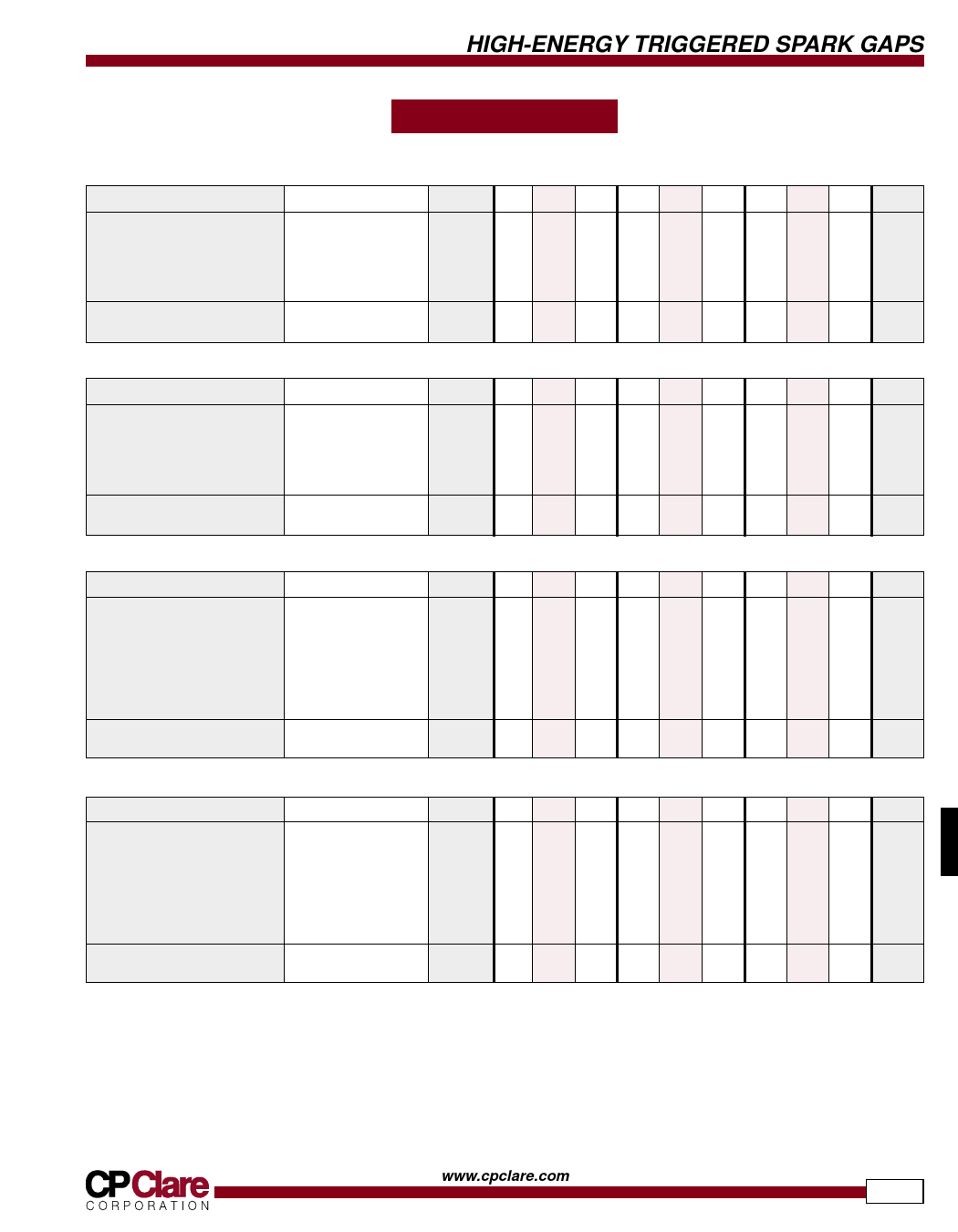
SPECIFICATIONS
Triggergaps
All characteristics at 25˚C
PARAMETER
Device Specifications
Self-Breakdown Voltage
Applied Voltage
Trigger Voltage1
Dimension A
Life Ratings
Discharge Life2
CONDITIONS
TA-1.0
TA-2.0
TA-5.0
SYMBOL MIN TYP MAX MIN TYP MAX MIN TYP MAX UNITS
100V/s
tr=0.5µs, PW=3.0µs
≥1000 shots into .2Ω
EZ
0.9 1.0 1.1 1.8 2.0 2.2 4.5 5.0 5.5 kV
Ebb
0.4 - 0.85 0.7 - 1.7 1.2 - 4.2 kV
e
3.0 - 2.5 3.0 - 2.5 3.5 - 2.5 kV pk
trig
- 0.687 0.750 0.813 0.697 0.760 0.823 0.697 0.760 0.823 inches
-
45 -
- 50 -
- 50 -
-
J
PARAMETER
Device Specifications
Self-Breakdown Voltage
Applied Voltage
Trigger Voltage1
Dimension A
Life Ratings
Discharge Life2
CONDITIONS
TA-7.0
TA-10.0
TA-15.0
SYMBOL MIN TYP MAX MIN TYP MAX MIN TYP MAX UNITS
100V/s
tr=0.5µs, PW=3.0µs
≥1000 shots into .2Ω
EZ
6.3 7.0 7.7 9.0 10.0 11.0 13.5 15.0 16.5 kV
Ebb
1.9 - 5.8 3.5 - 8.5 7.0 - 12.5 kV
etrig
3.7 -
2.8 5
- 3.5 8.0 - 4.5 kV pk
- 0.697 0.760 0.823 0.727 0.790 0.853 0.767 0.830 0.893 inches
-
50 -
- 60 -
- 70 -
-
J
PARAMETER
Device Specifications
Self-Breakdown Voltage
Applied Voltage
Trigger Voltage1
Dimension A
Dimension B
Dimension C
Life Ratings
Discharge Life2
CONDITIONS
TB-2.5
TB-5.0
TB-10.0
SYMBOL MIN TYP MAX MIN TYP MAX MIN TYP MAX UNITS
100V/s
tr=0.5µs, PW=3.0µs
discharges into .3Ω
EZ 2.25 2.50 2.75 4.5 5.0 5.5 9.0 10.0 11.0 kV
Ebb
0.8 - 2.0 1.5 - 4.0 3.0 - 8.0 kV
etrig
3.1 -
1.8 3.2
-
1.9 4.6
-
2.1 kV pk
-
- 1.99 -
- 1.99 -
- 1.99 - inches
-
- - 0.23 -
- 0.23 -
- 0.58 inches
-
- - 2.03 -
- 2.03 -
- 2.10 inches
-
150 -
- 150 -
- 300 -
-
J
PARAMETER
Device Specifications
Self-Breakdown Voltage
Applied Voltage
Trigger Voltage1
Dimension A
Dimension B
Dimension C
Life Ratings
Discharge Life2
CONDITIONS
TB-15.0
TB-20.0
TB-25.0
SYMBOL MIN TYP MAX MIN TYP MAX MIN TYP MAX UNITS
100V/s
tr=0.5µs, PW=3.0µs
discharges into .3Ω
EZ 13.5 15.0 16.5 18.0 20.0 22.0 22.5 25.0 27.5 kV
Ebb
4.5 - 12.0 6.0 - 16.0 7.5 - 20.0 kV
etrig
6.3 -
3.5 8.0
-
4.5 9.7
-
5.2 kV pk
-
- 2.67 -
- 2.79 -
- 2.79 - inches
-
- - 0.58 -
- 0.58 -
- 0.58 inches
-
- - 2.10 -
- 2.10 -
- 2.10 inches
-
300 -
- 300 -
- 300 -
-
J
1 The trigger voltages given in these tables are the minimum triggering voltages necessary for triggering at the corresponding applied voltage limits. As the applied trigger voltage
increases, the trigger voltage required for triggering decreases. It is assumed that the trigger is applied across the trigger and adjacent main electrodes — higher trigger voltages are
required if it is applied across the trigger voltage and opposite main electrodes.
2 End point for life testing is a 15% reduction in the self-breakdown voltage.
3 Because the self-breakdown voltage of these devices is adjustable, the trigger voltage required for any particular applied voltage cannot be specified. Clare suggests setting the self-
breakdown voltage to at least 115% of the maximum applied voltage.
www.cpclare.com
559
Share Link: 