PBL38541/1SO データシートの表示(PDF) - Ericsson
部品番号
コンポーネント説明
メーカー
PBL38541/1SO Datasheet PDF : 14 Pages
| |||
PBL 385 41
PBL
385 41 constant
current
generator
11
DC-
load
DC
( ref. ≈ 1.2V )
ref. minus
a diode ≈ 0.5V
AC-
load
DC-load = R4+R5
AC-load = R4+R5//ZTI
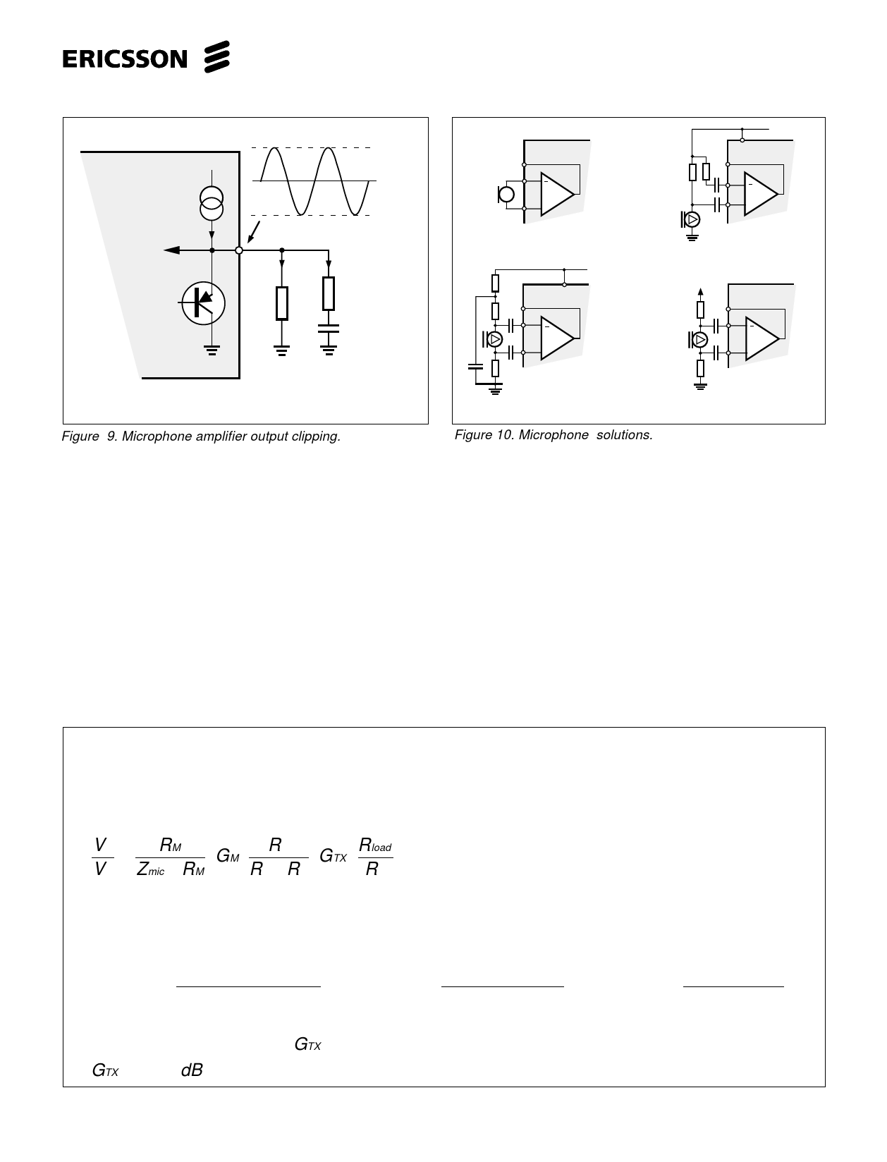
Figure 9. Microphone amplifier output clipping.
Transmitter amplifier
(a)
PBL 385 41
11
12
M
13 +
Dynamic
microphone
R
C+
(c)
11
4
PBL 385 41
12
M
13 +
Balanced electret microphone.
An additional RC filterlink is
recommended if pin 4 is used
as a supply.
(b)
4 PBL 385 41
11
12
M
13 +
Unbalanced electret
mic. with balanced
signal, DC-supply from
pin 4.
DC
Pin 8 or9.
(d)
11
12
PBL 385 41
M
13 +
Balanced electret
microphone
Figure 10. Microphone solutions.
The transmitter amplifier in PBL38541 consists of three stages. The first stage is an amplitude limiter for the input signal at TI, in
order to prevent the transmitted signal to exceed a certain set level and cause distortion. The second stage amplifies further the signal
from the first and adds it to a DC level from an internal DC-regulation loop in order to give the required DC characteristic to the telephone
set. The output of this stage is TO. The third stage is a current generator that presents a high impedance towards the line and has its
gain from TO to +L. The gain of this amplifier is ZL/R6 where ZL is the impedance across the telephone line. Hence, the absolute
maximum signal amplitude that can be transmitted to the line undistorted is dependent of R6. (amplitude limiting)
The transmitter gain and frequency response are set by the RC-network between the pins 11 and 3. See fig.11. The capacitor
for cutting the high end of frequency band is best to be placed directly at the microphone where it also will act as a RFI suppressor.
The input signal source impedance to the transmitter amplifier input TI should be reasonably low in order to keep the gain spread down,
saying that R4//R5 (see fig. 4) must be at least a factor 5 lower than the ZTin. Observe that the capacitor C1 should have a reasonably
good temperature behaviour in order to keep the impedance rather constant. The V+C´s influence on the transmitter DC-characteristic
is shown in the fig.8 (DC-characteristic), therefore the transmitter gain would change if the transmitted signal gives reason to an ac-
voltage leak signal across C1 since this is a feedback point. If the transmitter has an unacceptable low sving to the line at low line
currents <≈10mA the first step should be to examine if the circuits DC characteristic can be adjusted upwards.
How to calculate the gains in the transmitter channel.
See fig. 2 and 4.
Microphone amplifiers first stage 19 dB.
Microphone amplifiers regulated second stage 10.5 dB - 15.5 dB
Regulation interval 10.5 - 15.5 dB
low gain 19.0 + 10.5 dB = 29.5 dB
high gain 19.0 + 15.5 dB = 34.5 dB
V2 =
RM
⋅ GM ⋅ R 5 ⋅ GTX ⋅ Rload
V 3 Zmic + RM
R4 +R5
R6
RM = Microphone amplifier input resistance
Rload = Rline // Rtelephone
ex. calculate the gain of the transmitter stage GTX at 0 - line length:
43 = 20 log( (1.7 / /2.7)k ) + 29.5 + 20 log( (17 / /22)k ) + GTX + 20 log( 600Ω / /910Ω )
350Ω + (1.7 / /2.7)k
18k + (17 / /22)k
75Ω
43 = −2.51+ 29.5 − 9.17 + GTX + 13.66
GTX = 11.52dB
7
Share Link: 