9551 データシートの表示(PDF) - NXP Semiconductors.
部品番号
コンポーネント説明
メーカー
9551 Datasheet PDF : 26 Pages
| |||
NXP Semiconductors
PCA9551
8-bit I2C-bus LED driver with programmable blink rates
6.3.6 LS0 to LS1 - LED selector registers
The LSn LED select registers determine the source of the LED data.
00 = output is set LOW (LED on)
01 = output is set high-impedance (LED off; default)
10 = output blinks at PWM0 rate
11 = output blinks at PWM1 rate
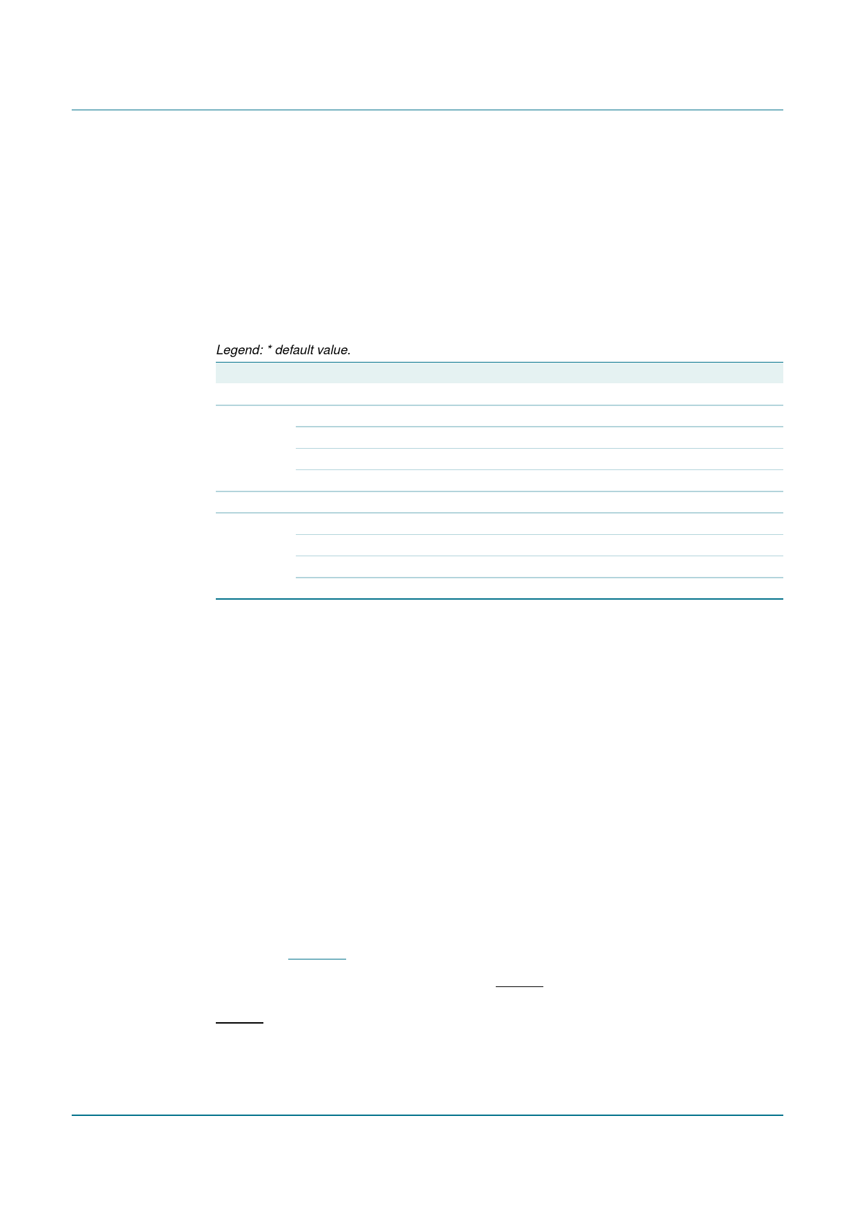
Table 9. LS0 to LS1 - LED selector registers bit description
Legend: * default value.
Register Bit
Value
Description
LS0 - LED0 to LED3 selector
LS0
7:6
01*
LED3 selected
5:4
01*
LED2 selected
3:2
01*
LED1 selected
1:0
01*
LED0 selected
LS1 - LED4 to LED7 selector
LS1
7:6
01*
LED7 selected
5:4
01*
LED6 selected
3:2
01*
LED5 selected
1:0
01*
LED4 selected
6.4 Pins used as GPIOs
LED pins not used to control LEDs can be used as general purpose I/Os (GPIOs).
For use as input, set LEDn to high-impedance (01) and then read the pin state via the
Input register.
For use as output, connect external pull-up resistor to the pin and size it according to the
DC recommended operating characteristics. LEDn output pin is HIGH when the output is
programmed as high-impedance, and LOW when the output is programmed LOW through
the ‘LED selector’ register. The output can be pulse-width controlled when PWM0 or
PWM1 are used.
6.5 Power-on reset
When power is applied to VDD, an internal Power-On Reset (POR) holds the PCA9551 in
a reset condition until VDD has reached VPOR. At that point, the reset condition is released
and the PCA9551 registers are initialized to their default states, all the outputs in the
OFF state. Thereafter, VDD must be lowered below 0.2 V to reset the device.
6.6 External RESET
A reset can be accomplished by holding the RESET pin LOW for a minimum of tw(rst). The
PCA9551 registers and I2C-bus state machine will be held in their default states until the
RESET input is once again HIGH.
This input requires a pull-up resistor to VDD if no active connection is used.
PCA9551_8
Product data sheet
Rev. 08 — 31 July 2008
© NXP B.V. 2008. All rights reserved.
7 of 26
Share Link: 