PCF85103C-2(2002) гГЗгГЉгВњгВЈгГЉгГИгБЃи°®з§ЇпЉИPDFпЉЙ - Philips Electronics
йГ®еУБзХ™еПЈ
гВ≥гГ≥гГЭгГЉгГНгГ≥гГИи™ђжШО
гГ°гГЉгВЂгГЉ
PCF85103C-2 Datasheet PDF : 20 Pages
| |||
Philips Semiconductors
PCF85103C-2
256 √Ч 8-bit CMOS EEPROM with I2C-bus interface
11. I2C-bus characteristics
Table 7: I2C-bus characteristics
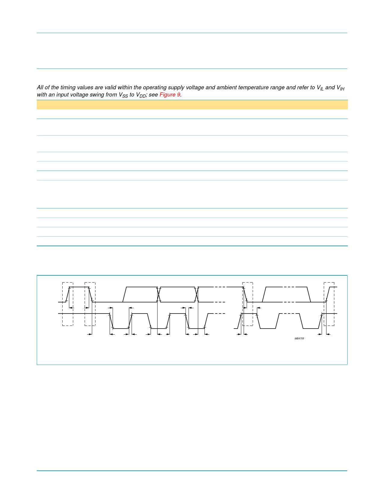
All of the timing values are valid within the operating supply voltage and ambient temperature range and refer to VIL and VIH
with an input voltage swing from VSS to VDD; see Figure 9.
Symbol
Parameter
Conditions
Min
Max
Unit
fSCL
clock frequency
tBUF
bus free time between a STOP and
START condition
0
100
kHz
4.7
вИТ
µs
tHD;STA
START condition hold time after
which пђБrst clock pulse is generated
4.0
вИТ
µs
tLOW
tHIGH
tSU;STA
LOW level clock period
HIGH level clock period
set-up time for START condition
repeated start
4.7
вИТ
µs
4.0
вИТ
µs
4.7
вИТ
µs
tHD;DAT
data hold time
for bus compatible masters
5
вИТ
µs
for bus devices
[1]
0
вИТ
ns
tSU;DAT
tr
tf
tSU;STO
data set-up time
SDA and SCL rise time
SDA and SCL fall time
set-up time for STOP condition
250
вИТ
ns
вИТ
1
µs
вИТ
300
ns
4.0
вИТ
µs
[1] The hold time required (not greater than 300 ns) to bridge the undeпђБned region of the falling edge of SCL must be internally provided by
a transmitter.
SDA
t BUF
t LOW
SCL
P
S
t HD;STA
tr
t HD;DAT
P = STOP condition; S = START condition.
Fig 9. Timing requirements for the I2C-bus.
tf
t HIGH
t SU;DAT
t HD;STA
S
t SU;STA
MBA705
P
t SU;STO
9397 750 09646
Product data
Rev. 02 вАФ 09 May 2002
© Koninklijke Philips Electronics N.V. 2002. All rights reserved.
11 of 20
Share Link: 