HT827A0 データシートの表示(PDF) - Holtek Semiconductor
部品番号
コンポーネント説明
メーカー
HT827A0 Datasheet PDF : 49 Pages
| |||
HT827A0
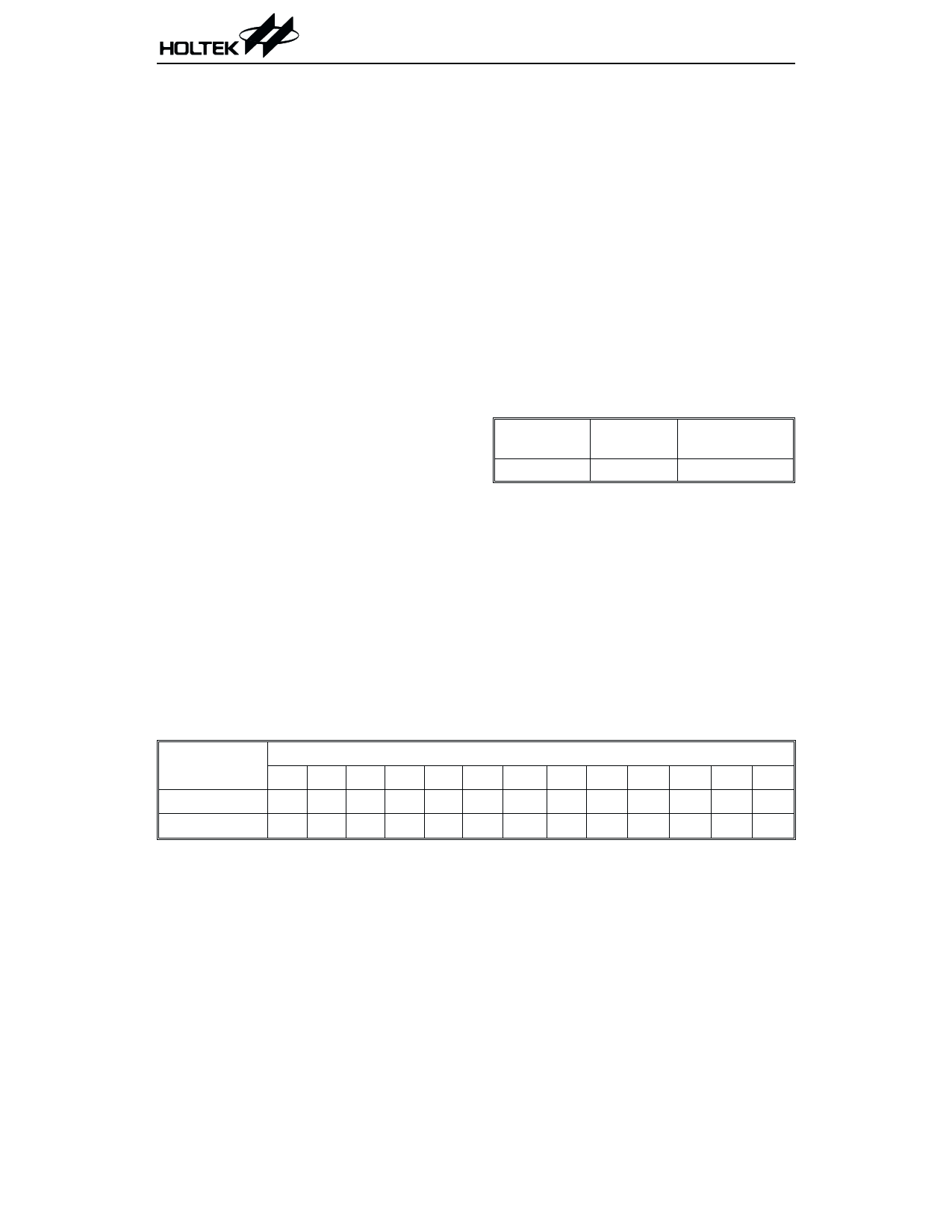
· Table location
Any location in the program ROM can be used
as a look-up table. The instructions
²TABRDC [m]² (the current page, 1 page=256
words) and ²TABRDL [m]² (the last page)
transfer the contents of the lower-order byte
to the specified data memory, and the
higher-order byte to TBLH (08H). Only the
destination of the lower-order byte in the ta-
ble is well-defined. The other bits of the table
word are transferred to the lower portion of
TBLH. The higher-order byte register
(TBLH) of the table is read only. The table
pointer (TBLP), on the other hand, is a
read/write register (07H) indicating the table
location. This location must be placed in
TBLP before accessing the table. All the table
related instructions require 2 cycles to com-
plete an operation. These areas may function
as a normal program memory depending
upon the user¢s requirements.
Stack register - Stack
The stack register is a special part of the mem-
ory used to save the contents of the program
counter (PC). This stack is organized into 8 lev-
els. It is neither part of the data nor program
space, and cannot be read or written to. Its acti-
vated level is indexed by a stack pointer (SP)
and cannot be read or written to. At a subrou-
tine call or interrupt acknowledgment, the con-
tents of the program counter are pushed onto
the stack. The program counter is restored to
its previous value from the stack at the end of a
subroutine or interrupt routine, which is sig-
naled by a return instruction (RET or RETI).
After a chip resets, SP will point to the top of
the stack.
The interrupt request flag will be recorded but
the acknowledgment will be inhibited when the
stack is full and a non-masked interrupt takes
place. After the stack pointer is decremented
(by RET or RETI), the interrupt will be ser-
viced. This feature prevents stack overflow and
allows programmers to use the structure more
easily. In a similar case, if the stack is full and a
²CALL² is subsequently executed, stack over-
flow occurs and the first entry is lost.
Data memory - RAM
The data memory is further divided into two
functional groups, namely, special function reg-
isters and general purpose data memories. Al-
though most of them can be read or be written
to, some are read only.
The data memory size for HT827A0 is shown as
follows.
Pard No.
Special
General
RAM RAM Address
HT827A0 00H~2FH
30H~FFH
The special function registers include an indi-
rect addressing register (00H), timer/event
counter high byte register (TMRH; 0FH),
timer/event counter low byte register (TMRL;
10H); timer/event counter control register
(TMRC; 11H), program counter lower-order
byte register (PCL; 06H), memory pointer reg-
ister (MP; 01H), accumulator (ACC; 05H), table
pointer (TBLP; 07H), table higher-order byte
register (TBLH; 08H), status register
(STATUS; 0AH), interrupt control register
(INTC; 0BH), watchdog timer option setting
register (WDTS; 09H), I/O registers (PA; 12H,
PB; 14H, PC; 16H, PD; 18H, PE; 1AH) and I/O
Table Location
Instruction(s)
*12 *11 *10 *9 *8 *7 *6 *5 *4 *3 *2 *1 *0
TABRDC [m] P12 P11 P10 P9 P8 @7 @6 @5 @4 @3 @2 @1 @0
TABRDL [m] 1 1 1 1 1 @7 @6 @5 @4 @3 @2 @1 @0
Note: *12~*0: Bits of table location
@7~@0: Bits of table pointer
Table location
P12~P8: Bits of current program counter
10
March 15, 2000
Share Link: 