HT827A0 データシートの表示(PDF) - Holtek Semiconductor
部品番号
コンポーネント説明
メーカー
HT827A0 Datasheet PDF : 49 Pages
| |||
HT827A0
WDT prescaler, a longer time-out period can be
attained. Writing data to WS2, WS1 and WS0
(bits 2, 1 and 0 of WDTS) can derive different
time-out periods. If WS2, WS1 and WS0 are all
equal to 1, the division ratio is up to 1:128, and
the maximum time-out period is 2.6 seconds.
WS2 WS1 WS0 Division Ratio
0
0
0
1:1
0
0
1
1:2
0
1
0
1:4
0
1
1
1:8
1
0
0
1:16
1
0
1
1:32
1
1
0
1:64
1
1
1
1:128
WDTS register
If the WDT oscillator is disabled, the WDT clock
may still come from an instruction clock. It oper-
ates in the same manner except that WDT may
stop counting and loses its protecting purpose in
the HALT state. In this situation the logic can
only be re-initialized by external logic. The high
nibble and bit 3 of WDTS are reserved for user¢s
defined flags. The programmer may use these
flags to indicate some specified statuses.
The on-chip RC oscillator (WDT OSC) is
strongly recommended if the device operates in
a noisy environment, since the HALT function
will stop the system clock.
Overflow of the WDT under a normal operation
initializes a ²chip reset² and sets the status bit
²TO². It will initialize a ²warm reset², and only
PC and SP are reset to zero in the HALT mode.
To clear the contents of WDT (including the
WDT prescaler), three methods are adopted,
namely, external reset (a low level to RES),
software instructions, and ²HALT² instruction.
The software instructions include ²CLR WDT²
and the other sets - ²CLR WDT1² and ²CLR
WDT2². Of these two types of instructions, by
mask option only one can be active at a time -
²CLR WDT times selection option². If ²CLR
WDT² is chosen (i.e., CLRWDT times equal
one), any execution of the ²CLR WDT² instruc-
tion will clear WDT. In the case that ²CLR
WDT1² and ²CLR WDT2² are selected (i.e.,
CLRWDT times equal two), these two instruc-
tions must be executed to clear WDT; otherwise
WDT may reset the chip as a result of time-out.
Power down operation - HALT
The HALT mode is initialized by the ²HALT²
instruction and results in the following:
· The system oscillator is turned off but the
WDT oscillator still keeps running (if the
WDT oscillator is selected).
· The contents of the on-chip RAM and regis-
ters remain unchanged.
· The WDT and WDT prescaler are cleared and
re-counted (if the clock of WDT is from the
WDT oscillator).
· All the I/O ports maintain their original
statuses.
· The PD flag is set and the TO flag cleared.
The system can quit the HALT mode by an exter-
nal reset, interrupt, external falling edge signal
on port A or WDT overflow. An external reset
leads to device initialization and a WDT overflow
performs a ²warm reset². The reason for chip re-
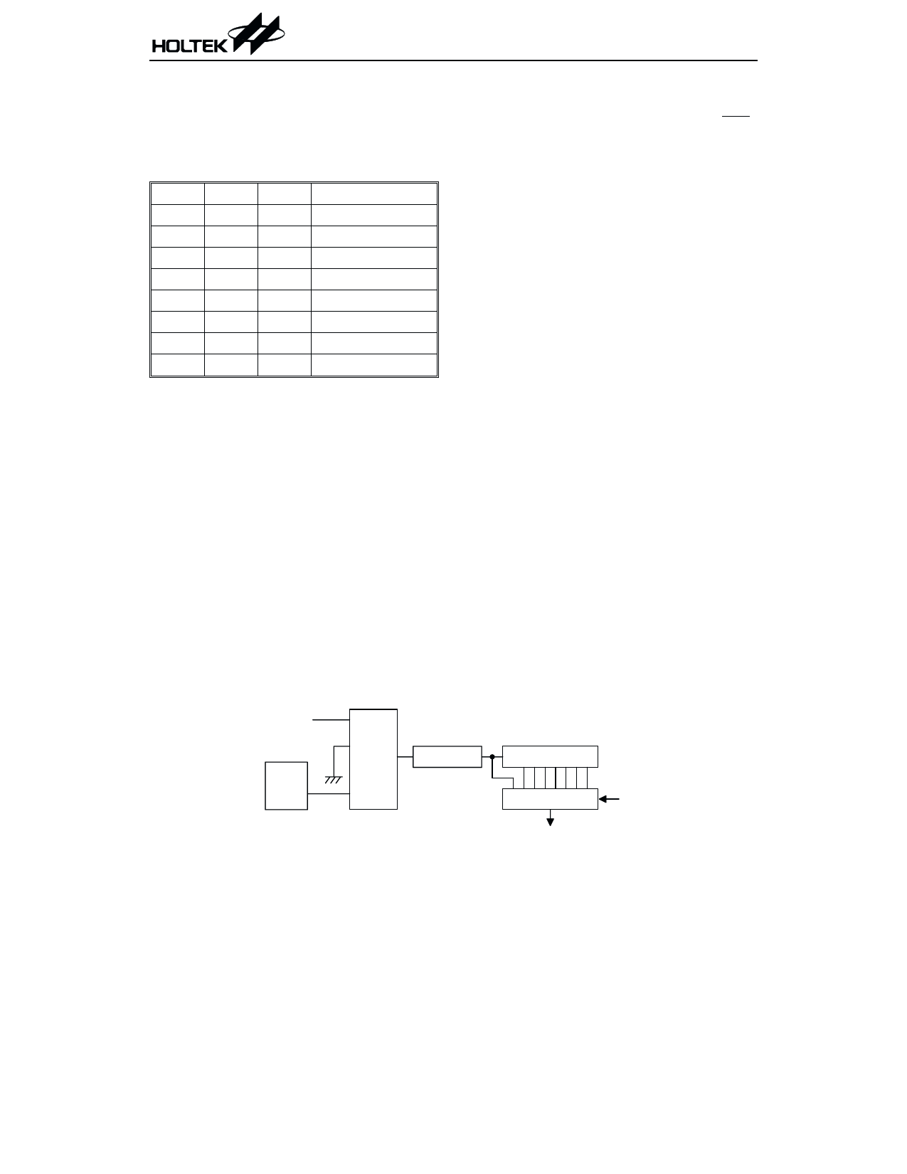
S y s te m C lo c k /4
W DT
O SC
M ask
O p tio n
S e le c tio n
8 - b it C o u n te r
W D T P r e s c a le r
7 - b it C o u n te r
8 -to -1 M U X
W S 0~W S 2
W D T T im e - o u t
Watchdog timer
15
March 15, 2000
Share Link: 