HT827A0 データシートの表示(PDF) - Holtek Semiconductor
部品番号
コンポーネント説明
メーカー
HT827A0 Datasheet PDF : 49 Pages
| |||
One of the relative counter values is preloaded
to the sampling rate counter after a code is
written to the counter (SRC; 23H). Once the
sampling rate counter starts counting, it will
count from its current contents to 1FH. The
counter is reloaded from the sampling rate
counter preload register, and generates an in-
terrupt request flag (SRF; bit 5 of INTC) if over-
flow of the divide-by-1 counter occurs.
To enable a counting operation, the ON bit
(SRON; bit 7 of TEMPO) of the counter should
be set to 1. Overflow of the sampling rate coun-
ter is one of the wake-up sources. Writing a ²0²
to ESI will disable the interrupt service.
Writing data to the sampling rate preload regis-
ter will also reload the data to the sampling
rate counter in the case of 1F condition of the
sampling rate counter. On the other hand, data
written to the sampling rate counter will be
kept only in the counter preload register if the
counter is turned on. The sampling rate counter
still goes on working till an overflow of the di-
vide-by-1 counter occurs.
HT827A0
The clock is blocked to avoid errors once the
sampling rate counter is read. The programmer
should take the counting error into account
since blocking of the clock may result in a
counting error.
Timer/event counter
The HT827A0 provides a timer/event counter.
This timer contains an 8-bit/16-bit programma-
ble count-up counter. The clock may come from
an external source or from the system clock di-
vided by 4. Only one reference time-base is avail-
able when an internal instruction clock is
selected. The external clock input allows the
user to count external events, measure time in-
tervals or pulse widths, or generate an accurate
time base.
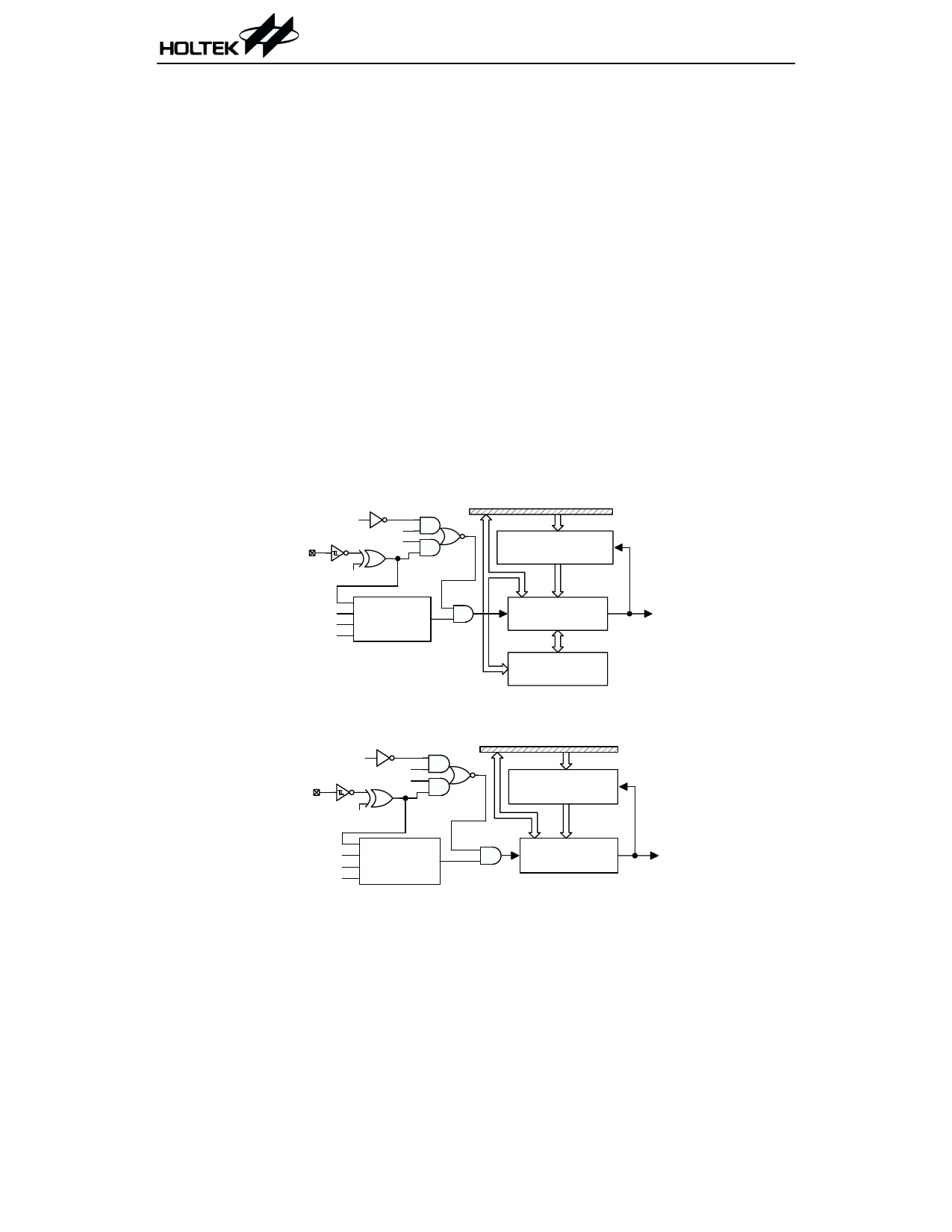
For the 16-bit timer/event counter, there are
three registers related to the timer/event counter,
namely, TMRH ([0FH]), TMRL ([10H]) and
TMRC ([11H]). Three physical registers are
mapped to the TMR location. Writing TMRL only
writes the data into a low byte buffer, and writing
S y s te m C lo c k /4
TM 1
TM R 0
TM 0
TM R 1
TE
T im e r /e v e n t C o u n te r
P r e lo a d R e g is te r
D ATA BU S
R E LO A D
P u ls e W id th
TM 1
M e a s u re m e n t
TM 0
M o d e C o n tro l
TO N
T im e r /e v e n t
C o u n te r
L o w B y te
B u ffe r
O V E R FLO W
T o In te rru p t
16-bit Timer/event counter
S y s te m C lo c k /4
TM 1
TM 0
TM R
TE
D ATA BU S
T im e r /e v e n t C o u n te r R E L O A D
P r e lo a d R e g is te r
TM 1
TM 0
P u ls e W id th
M e a s u re m e n t
M o d e C o n tro l
TO N
T im e r /e v e n t
C o u n te r
O V E R FLO W
T o In te rru p t
8-bit Timer/event counter
20
March 15, 2000
Share Link: 