HT827A0 データシートの表示(PDF) - Holtek Semiconductor
部品番号
コンポーネント説明
メーカー
HT827A0 Datasheet PDF : 49 Pages
| |||
HT827A0
Functional Description
Executive flow
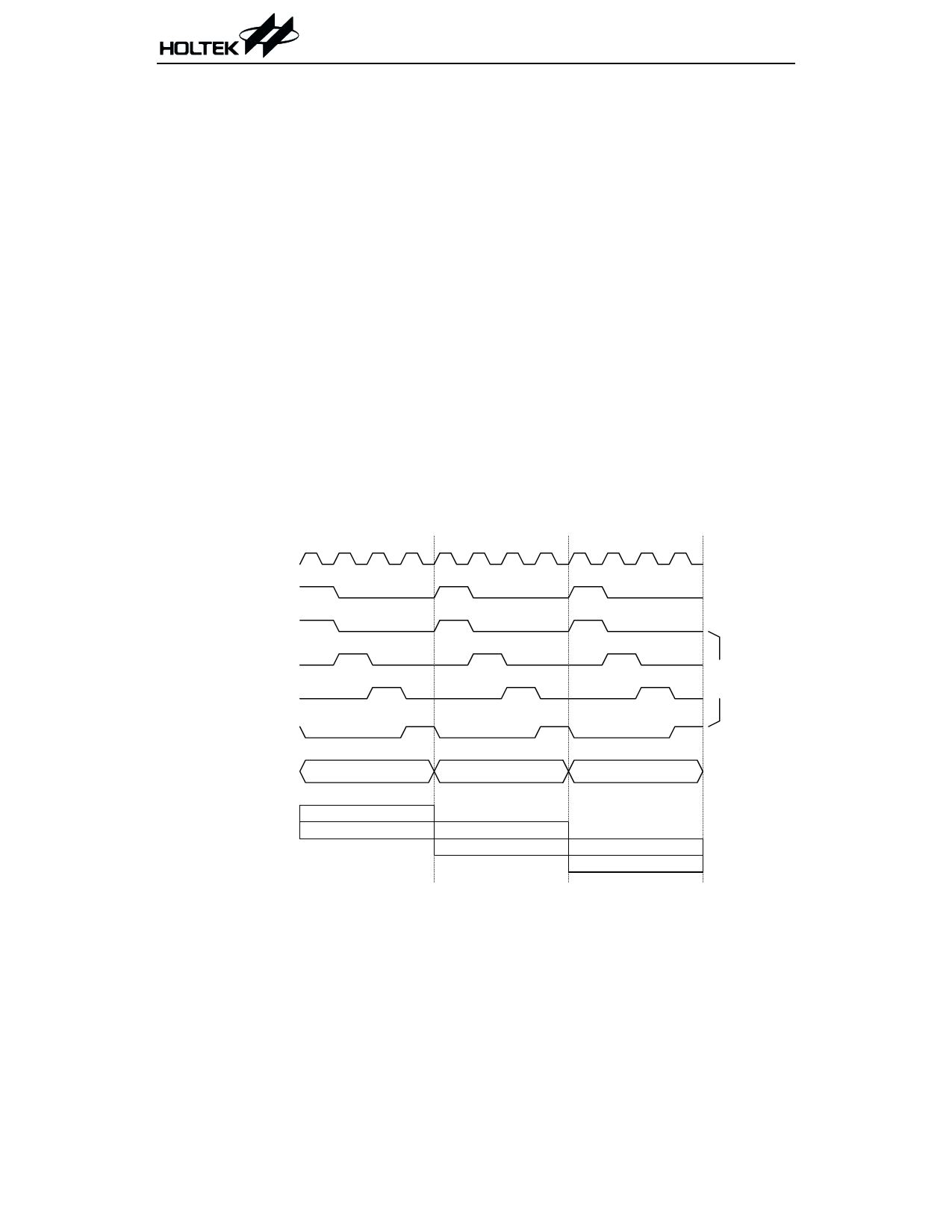
The HT827A0 provides a system clock which is
derived from a crystal or an RC type of oscillator.
The clock is internally divided into four
non-overlapping clocks denoted by P1, P2, P3 and
P4. An instruction cycle consists of T1~T4.
Instruction fetching and execution are
pipelined in such a way that a fetch takes an in-
struction cycle while decoding and execution
take the next instruction cycle. The pipelining
scheme causes each instruction to execute ef-
fectively in a cycle. If an instruction changes
the program counter, two cycles are required to
complete that instruction.
Program counter - PC
The program counter (PC) controls the se-
quence in which the instructions stored in the
program ROM are executed.
The contents of the program counter are incre-
mented by one after a program memory word is
accessed to fetch an instruction code. The pro-
gram counter then points to a memory word
containing the next instruction code.
The PC manipulates a program transfer by
loading the address corresponding to each in-
struction when executing a jump instruction,
conditional skip execution, loading PCL regis-
ter, subroutine call, initial reset, internal inter-
rupt, external interrupt or return from
subroutine.
The conditional skip is activated by instructions.
Once the condition is satisfied, the next instruc-
tion, fetched during the current instruction exe-
cution, is discarded and a dummy cycle replaces
it to get a proper instruction. Otherwise, the sys-
tem will proceed with the next instructions.
The lower byte of the program counter (PCL) is
a readable and writable register (06H). Moving
data into PCL performs a short jump. The desti-
nation is within 256 locations.
Once a control transfer takes place, the execu-
tion suffers from an additional dummy cycle.
T1 T2 T3 T4 T1 T2 T3 T4 T1 T2 T3 T4
S y s te m C lo c k
O S C 2 ( R C o n ly )
P1
P2
In te rn a l
P hase
P3
C lo c k s
P4
PC
PC
PC +1
PC +2
F e tc h IN S T (P C )
E x e c u te IN S T (P C -1 )
F e tc h IN S T (P C + 1 )
E x e c u te IN S T (P C )
F e tc h IN S T (P C + 2 )
E x e c u te IN S T (P C + 1 )
Execution flow
8
March 15, 2000
Share Link: 