HT827A0 データシートの表示(PDF) - Holtek Semiconductor
部品番号
コンポーネント説明
メーカー
HT827A0 Datasheet PDF : 49 Pages
| |||
HT827A0
Program memory - ROM
The program memory stores the to-be-executed
program instructions. It also includes data, ta-
ble and interrupt entries, addressed by the pro-
gram counter along with the table pointer.
The program memory size for HT827A0 is
8K´16.
Certain locations in the program memory are
reserved for special usage:
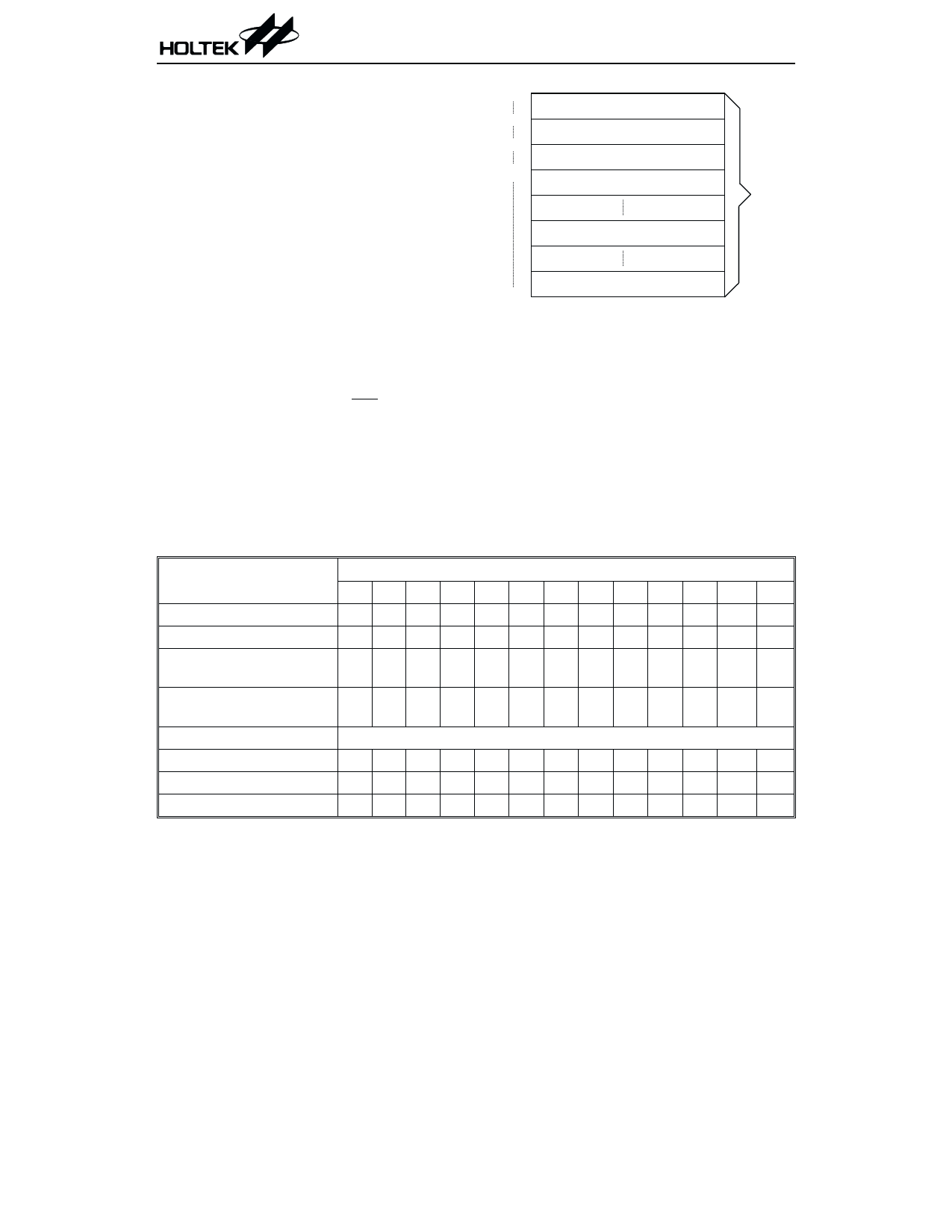
· Location 000H
This area is reserved for program initializa-
tion. The program always begins execution at
location 000H each time the system is reset.
· Location 004H
This area is reserved for an external interrupt
service program. The program begins execu-
tion at location 004H if the INT input pin is
activated, the interrupt is enabled and the
stack is not full.
· Location 008H
This area is reserved for a voice sampling rate
counter interrupt service program. The pro-
gram begins execution at location 008H if a
timer interrupt results from a sampling rate
000H
D e v ic e in itia liz a tio n p r o g r a m
004H
E x te r n a l in te r r u p t s u b r o u tin e
008H
S a m p lin g r a te c o u n te r in te r r u p t s u b r o u tin e
00C H
T im e r /e v e n t c o u n te r in te r r u p t s u b r o u tin e
L o o k - u p ta b le ( 2 5 6 w o r d s )
P ro g ra m
ROM
1FFFH
L o o k - u p ta b le ( 2 5 6 w o r d s )
Program memory
counter overflow, the interrupt is enabled and
the stack is not full.
· Location 00CH
This area is reserved for a timer/event coun-
ter interrupt service program. The program
begins execution at location 00CH if an inter-
rupt results from a timer/event counter over-
flow, the interrupt is enabled and the stack is
not full.
Mode
Initial reset
External interrupt
Sampling rate counter
overflow
Timer/event counter
overflow
Skip
Loading PCL
Jump, call branch
Return from subroutine
Program Counter
*12 *11 *10 *9 *8 *7 *6 *5 *4 *3 *2 *1 *0
00000000000 0 0
00000000001 0 0
00000000010 0 0
00000000011 0 0
PC+2
*12 *11 *10 *9 *8 @7 @6 @5 @4 @3 @2 @1 @0
#12 #11 #10 #9 #8 #7 #6 #5 #4 #3 #2 #1 #0
S12 S11 S10 S9 S8 S7 S6 S5 S4 S3 S2 S1 S0
Note:
Program counter
*12~*0: Bits of program counter
#12~#0: Bits of instruction code
S12~S0: Bits of stack register
@7~@0: Bits of PCL
9
March 15, 2000
Share Link: 