4271 データシートの表示(PDF) - Peregrine Semiconductor Corp.
部品番号
コンポーネント説明
メーカー
4271 Datasheet PDF : 8 Pages
| |||
PE4271
Product Specification
Evaluation Kit
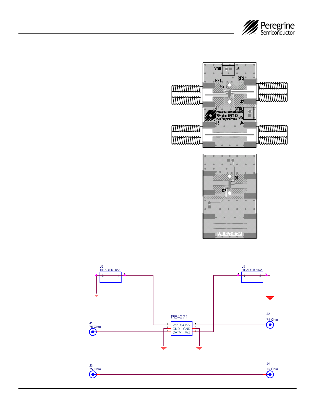
The PE4271 EK board was designed to ease
customer evaluation of Peregrine’s high
performance SPST CATV MOSFET switch. RF1
is connected through a 75 Ω transmission line via
the top left F connector, J1. RF2 is connected
through a 75 Ω transmission line via the top right
F connector, J2. A 75 Ω through transmission line
is available via F connectors J3 and J4. This
transmission line can be used to estimate the loss
of the PCB over the environmental conditions
being evaluated. VDD is supplied via J6-2, while
the control logic voltage is supplied via J5-2. It is
the responsibility of the customer to determine
proper supply decoupling for their design
application. It has been observed that by
removing C1 and C2 from the evaluation board
has not shown to degrade RF performance.
The board is constructed of a two metal layer FR4
material with a total thickness of 0.031”. The
bottom layer provides ground for the RF
transmission lines. The transmission lines were
designed using a coplanar waveguide model with
trace width of 0.021”, trace gaps of 0.030”,
dielectric thickness of 0.028”, metal thickness of
0.0021” and εr of 4.6. Note that the predominate
mode for these transmission lines is coplanar
waveguide with a ground plane.
Figure 11. Evaluation Board Layouts
Peregrine Specification 101/0167 (with F connectors)
Figure 12. Evaluation Board Schematic
Peregrine Specification 102/0245
Document No. 70-0149-03 │ www.psemi.com
©2005 Peregrine Semiconductor Corp. All rights reserved.
Page 5 of 8
Share Link: 