PG001 データシートの表示(PDF) - Allegro MicroSystems
部品番号
コンポーネント説明
メーカー
PG001 Datasheet PDF : 12 Pages
| |||
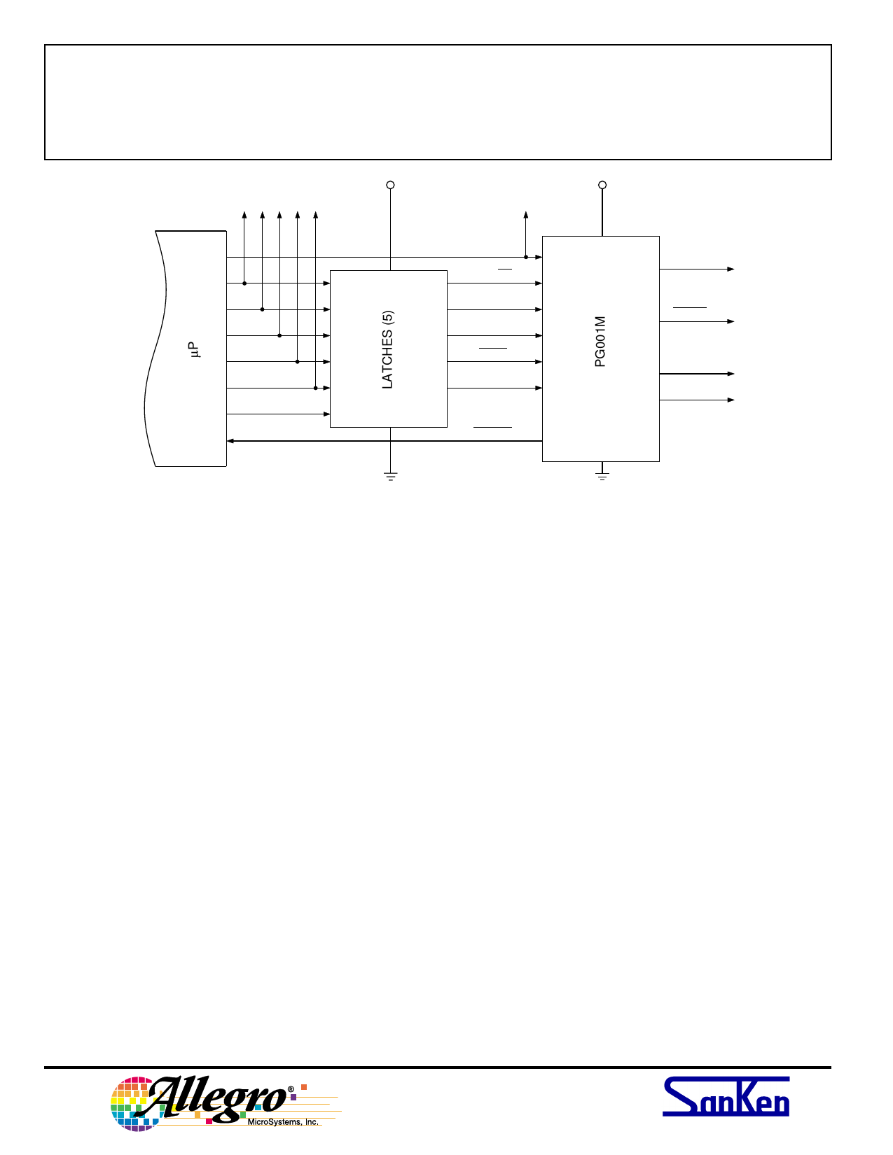
PG001M
PARALLEL-TO-SERIAL
DATA CONVERTER
STROBE
V CC
V CC
GND
+5 V
CLOCK IN
CCW/CW
MODE SELECT1
MODE SELECT2
RESET
VECTOR CONTROL
MONITOR
V DD
CLOCK
STROBE
SERIAL DATA A
SERIAL DATAB
GND
Dwg. EK-014-1
Figure 6 — A Latched Input-Bus Configuration
At start-up, reseting the counter adds only another
clock interval (per figures 4 and 5). During high-speed
slewing, the µP is only occupied with sending clock
signals and monitoring the readback (MO). Hence, of a
200 µs interval, with a slewing rate of 5 kHz, only 5 µs is
required to provide the clock input. At slower, more
typical step rates, 5 µs becomes an insignificant burden on
the µP controlling the stepping motor.
Other techniques to decrease and unburden the essen-
tial µP I/O lines and control logic are viable. Utilizing an
8-bit shift register (serial-to-parallel conversion) between
the µP and the controller IC further reduces the I/O lines,
and HCMOS logic provides serial-data entry at 20 MHz
(vs <200 kHz). Such a design could further decrease the
interval required to update the step-motor operation and
reduce the I/O lines on the bus.
115 Northeast Cutoff, Box 15036
™
Worcester, Massachusetts 01615-0036 (508) 853-5000
Share Link: 