PG001 データシートの表示(PDF) - Allegro MicroSystems
部品番号
コンポーネント説明
メーカー
PG001 Datasheet PDF : 12 Pages
| |||
PG001M
PARALLEL-TO-SERIAL
DATA CONVERTER
PG001M DESCRIPTION AND OPERATION
The PG001M is a CMOS step-motor control IC that
converts parallel-input signals from a microprocessor (µP,
or microcontroller, µC) to the serial-input data format
required for control of an SLA7042M or SLA7044M
microstepping, unipolar PWM, high-current motor driver.
This control IC offers five basic modes of motor operation:
1) normal 2-phase, full-step (100% torque vector);
2) 2-phase, full-step 'boosted' torque (141% vector);
3) 1/2-step, constant torque operation
(i.e., 2-1-2 switching);
4) 1/4-step operation with current-ratioed constant
torque; and
5) smooth microstepping operation (1/8th step) for
resonance-free motor performance (constant torque
with eight output current ratios).
Three inputs (VC, MS1, and MS2) control these five
operational modes (as shown in figure 1); this enables
designers to change the drive method during movement to
realize optimal performance.
Initially, at start-up, the high-torque mode can provide
141% torque (the resulting vector of both motor windings
at 100% current). This enhances rapid acceleration (and
deceleration). Switching to quarter-stepping or
microstepping (after initial, startup acceleration) offers
smooth, resonance-free operation during the ramp-up
interval. The transition to quarter- or microstepping
should occur before the increasing step rate approaches the
motor resonance frequency (usually 100 to 200 Hz).
The modes of operation and current-control truth table
are listed on page 2; and there are two full-step, 2-phase
(2-2) operating modes. The VECTOR CONTROL input
(VC) can only be changed when MONITOR (MO, a
readback pin) is LOW and the PG001M is operating in the
full-step mode. Starting (or stopping) the step motor with
VC HIGH delivers the highest torque (141%) from the
motor, and is the extension of two outputs ON at 71.4%.
This 'half-step' rotor position corresponds to the state when
MO is LOW, and switching the control inputs to another
operating mode is allowed.
The PG001M accepts logic signals from the µP and
converts these into the proper serial-data format required
to control the serial-data input lines of the SLA7042M or
SLA7044M microstepping power modules. The five
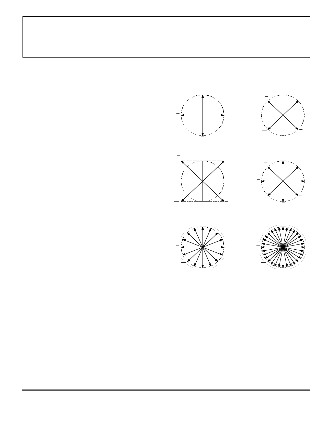
A
AB
AB
B
B
A
ONE-PHASE, FULL-STEP MODE
(WITHOUT PG001M)
AB
AB
AB
AB
TWO-PHASE, FULL-STEP MODE
(MS1 = L, MS2 = L, VC = L)
A
AB
AB
B
B
AB
AB
TWO-PHASE, FULL-STEP MODE
MAXIMUM TORQUE (141%)
(MS1 = L, MS2 = L, VC = H)
A
AB
AB
AB
AB
A
1/2-STEP MODE
CONSTANT TORQUE
(MS1 = H, MS2 = L, VC = X)
A
AB
AB
B
B
B
B
AB
AB
A
1/4-STEP MODE
(MS1 = L, MS2 = H, VC = X)
AB
AB
A
1/8-STEP MODE
(MS1 = H, MS2 = H, VC = X)
Dwg. OP-005
NOTE – Mode change only allowed at half-step positions (refer to
upper right figure).
Figure 1 — Current/Displacement Vectors
control inputs determine the various modes of operation.
The CLOCKOUT, SERIAL DATAA, SERIAL DATAB, and
STROBE to the SLA7042/44M are synchronized to the
CLOCKIN of the PG001M; and the CLOCKIN frequency is
eight times the step rate (more to follow on the signal/
timing relationships).
The internal logic and oscillator combine to convert
the parallel input signals to 'bursts' of serial data from the
Share Link: 