PG001 データシートの表示(PDF) - Allegro MicroSystems
部品番号
コンポーネント説明
メーカー
PG001 Datasheet PDF : 12 Pages
| |||
PG001M
PARALLEL-TO-SERIAL
DATA CONVERTER
+5 V
V BB
CLOCK IN
CCW/CW
MODE SELECT1
MODE SELECT2
RESET
VECTOR CONTROL
MONITOR
V DD
CONTROL SUPPLY
AABB
A
OUT
B
CLOCK
A
REF/ENABLE
B
A
STROBE
A
B
B
SERIAL DATA A
SERIAL DATA B
GND
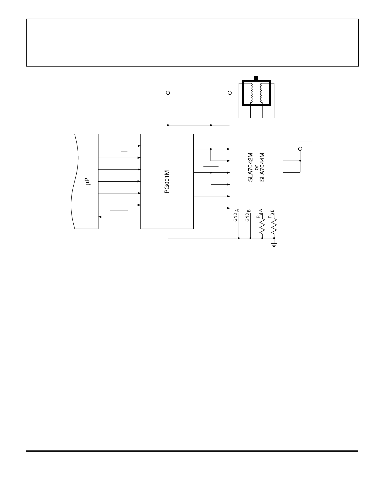
Figure 3 — Typical 'Integrated' Microstepping System
Dwg. EK-014A
Depicted in figure 4 are the 'front-end' I/O signals
(from RESET to VECTOR CONTROL), converted signals
from the controller IC to the microstepping power module
(CLOCKOUT, SERIAL DATAA, SERIAL DATAB, and
STROBE), plus the MONITOR (readback) to the
microcontroller. Finally, the power multi-chip module
current ratios are illustrated (OUTA and OUTB).
As shown, initially the counter is reset, and then the
motor is operating in quarter-step mode; then MS2 is
switched while MO is LOW. The two steps following are
full-step (100% torque vector). The final (fourth quadrant)
portion of figure 4 is the maximum (141%) torque mode,
after VECTOR CONTROL has been switched from LOW
to HIGH. Three of the five operational modes are shown,
and none require the µP to continually update the clock,
serial-data input, or strobe to the SLA7042/44M module.
The microstepping operation is illustrated in figure 5.
Initially the counter is reset, and with both MODE SE-
LECTs HIGH the controller is furnishing clock, serial
data, and strobe logic signals for 1/8th step increments.
After the RESET pulse, the first (two) full-steps in the
microstepping sequence, MS1 is switched LOW and the
control IC shifts into the 1/4-step mode. It becomes very
apparent that any microstepping directly from a µP to the
SLA7042/44M module 'burdens' the µP, complicates the
software, and might entail a 'dedicated' microcontroller in
many motion-control systems.
The PG001M controller IC precludes loading a µP
with direct serial-data signals to the power multi-chip
module. Because the step motor is updated at eight times
the step rate, this CMOS IC both simplifies software and
eliminates loading a system microprocessor with 'house-
keeping' control of step motors.
As illustrated in figures 4 and 5, the controller IC
eliminates the requirement to program the system for the
various modes of operation and the continual updating of
the serial-data signals to the power multi-chip module.
NOTE — In figures 4 and 5, the clock frequency is
constant during the few steps of operation that are shown
and half-step operation is not included.
Share Link: 