PG001 データシートの表示(PDF) - Allegro MicroSystems
部品番号
コンポーネント説明
メーカー
PG001 Datasheet PDF : 12 Pages
| |||
PG001M
PARALLEL-TO-SERIAL
DATA CONVERTER
RESET
CLOCK
IN
CCW/CW
MODE
SELECT1
MODE
SELECT 2
1/8-STEP MODE
1/4-STEP MODE
VECTOR
CONTROL
CLOCK
OUT
71.4 55.5 40
20
0
20
40 55.5 71.4 83
91 100 100 100 91
83 71.4
40
0
40
71.4
91
100
91
71.4
SERIAL
DATA A
71.4 83
91
100 100 100
91
83 71.4 55.5 40
20
0
20
40 55.5 71.4
91
100
91
71.4
40
0
40
71.4
SERIAL
DATAB
STROBE
MONITOR
PER CENT
OUT A
71.4 55.5 40
20
0
-20 -40 -55.5 -71.4 -83 -91 -100 -100 -100 -91
-83
-71.4
-40
0
40
71.4
91
100
91
71.4
FIRST QUADRANT
SECOND QUADRANT
THIRD QUADRANT
FOURTH QUADRANT
FIRST QUADRANT
PER CENT
OUT B
71.4 83
91
100
100 100
91
83 71.4 55.5
40
20
0
-20
-40 -55.5
-71.4
-91
-100
-91
-71.4
-40
0
40
71.4
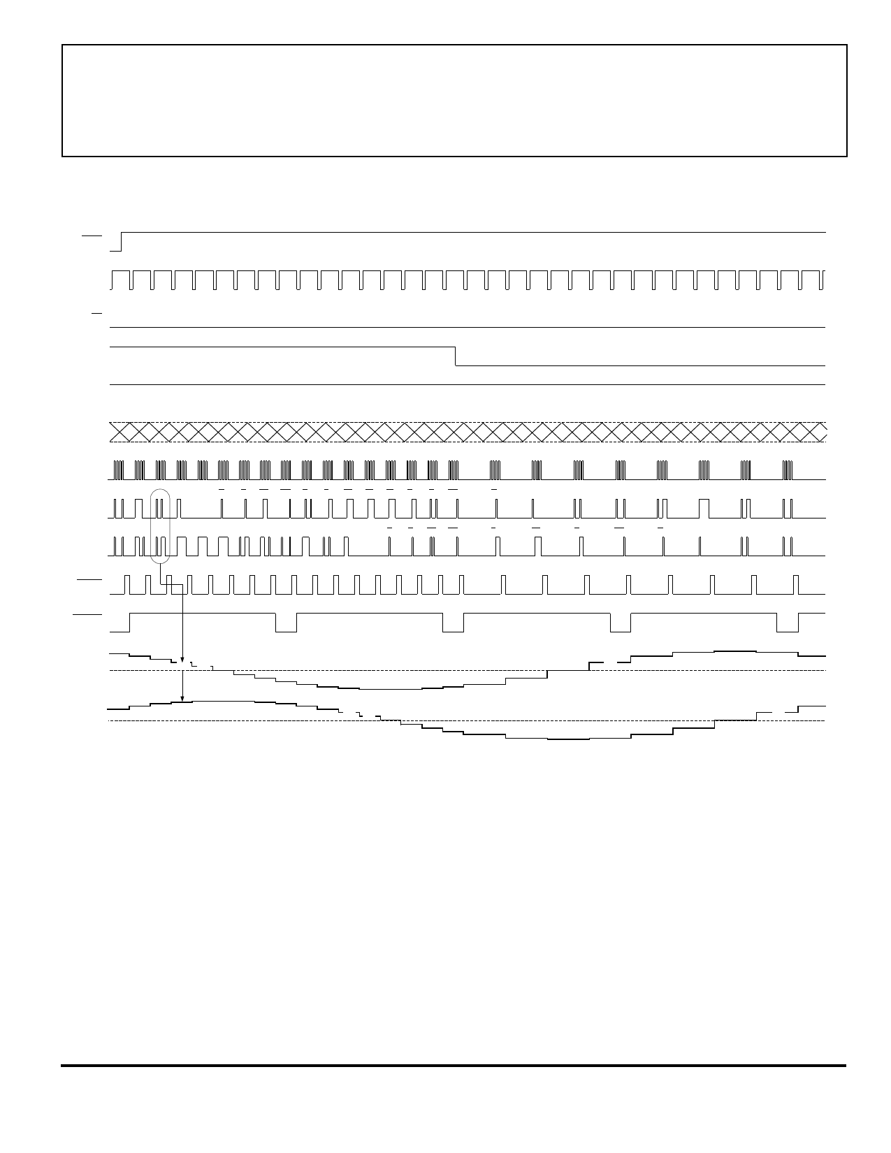
Figure 5 — Microstepping (1/8th-Step) and Quarter-Step Modes
Dwg. WK-006-1
One technique to free µP I/O lines for shared functions
is depicted in figure 6. The I/O lines required (without
latches) are then transformed into three 'dedicated' logic
inputs; a STROBE is added, and CLOCK and MONITOR
retained. CLOCK, RESET, MODE SELECT1, MODE
SELECT2, and VECTOR CONTROL now connect to a
bus.
The clock input frequency limit is derived from the
figure on page 3. The minimum period for the clock pulse
HIGH is 4.5 µs, plus a minimum LOW interval of 0.5 µs;
this limits the upper clock frequency to ≤200 kHz. Updat-
ing the operating mode of the controller IC requires only
one clock period (≥5 µs), and the five I/O lines on the bus
remain unchanged until a signal is required to change the
operating mode, reverse direction, vary torque, etc.
Share Link: 