DMC73CE167 データシートの表示(PDF) - Daewoo Semiconductor
部品番号
コンポーネント説明
メーカー
DMC73CE167 Datasheet PDF : 90 Pages
| |||
8Bit Single Chip Microcontroller
6
DMC73C167
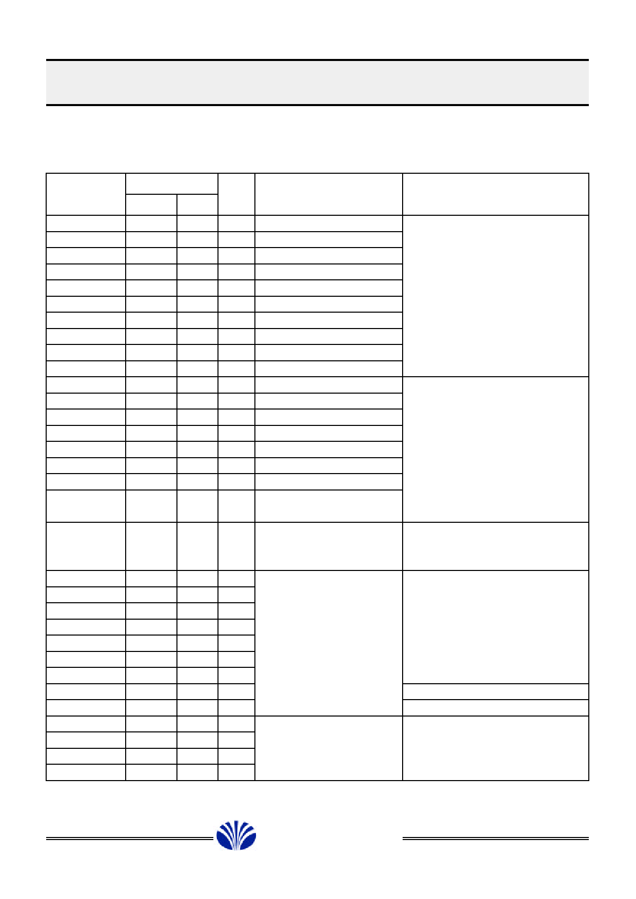
2.2 Pin Description
Pin
Symbol
PWM0
PWM1_0
PWM1_1
PWM1_2
PWM1_3
PWM1_4
PWM1_5
PWM1_6
PWM1_7
PWM1_8
B0/T1OUT
B1/T3OUT
B2
B3
B4
B5
B6
B7
A0
C0
C1
C2
C3
C4
C5
C6
VSS
C7
D0
D1
D2
D3
Pin Number
Primary SE
1
1
2
2
3
3
4
4
5
5
6
6
7
7
8
8
9
9
10
10
11
11
12
12
13
13
14
14
15
15
16
16
17
17
18
18
19
19
20
20
21
21
22
22
23
23
24
24
25
25
26
26
27
27
28
38
29
39
30
40
31
41
32
42
I/O
Function
Description
O 14-bit PWM output
CMOS output
O 6-bit PWM output 0
PWM1_0 to PWM1_8
O 6-bit PWM output 1
are output pins with
O 6-bit PWM output 2
+12V open drain
O 6-bit PWM output 3
O 6-bit PWM output 4
O 6-bit PWM output 5
O 6-bit PWM output 6
O 6-bit PWM output 7
O 6-bit PWM output 8
O Output, Timer 1 clock out B0 to B3 are optional use
O Output, Timer 3 clock out for open-drain output
O Output
with +12V buffer
O Output
O Output
B4 to B7 are optional use
O Output
for open-drain output with
O Output
12mA drive(+5V) or internal
O Output
pull up(+5V) resistor by mask
option
I/O ADC input or normal I/O 4-bit A/D converter or normal
I/O internal pull up(+5V)
resistor (mask option)
I/O Digital I/O
C0 to C7 are normal I/O pins
I/O
and internal resistors can be
I/O
optionally pulled up(+5V )
I/O
during masking process
I/O
I/O
I/O
I
Ground reference
I/O
I/O Digital I/O
D0 to D3 are normal I/O pins
I/O
and internal resistors can be
I/O
optionally pulled up(+5V)
I/O
during masking process
£Ä£Á£Å£×£Ï£Ï
DAEWOO ELECTRONICS CO., LTD.
Share Link: 