28F002BV データシートの表示(PDF) - Intel
部品番号
コンポーネント説明
メーカー
28F002BV Datasheet PDF : 55 Pages
| |||
E
2-MBIT SmartVoltage BOOT BLOCK FAMILY
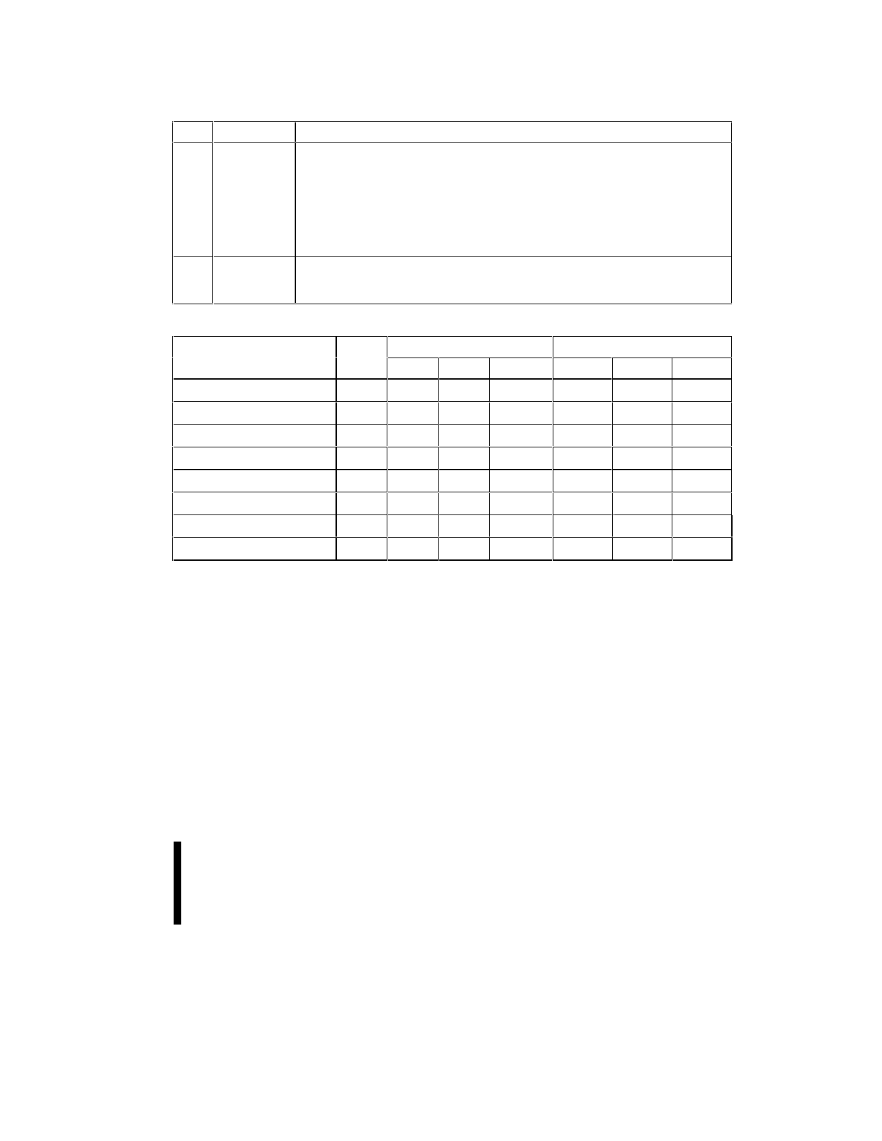
Table 6. Command Codes and Descriptions (Continued)
Code Device Mode
Description
50 Clear Status The WSM can only set the Program Status and Erase Status bits in the status
Register register to “1;” it cannot clear them to “0.”
The status register operates in this fashion for two reasons. The first is to give the
host CPU the flexibility to read the status bits at any time. Second, when
programming a string of bytes, a single status register query after programming the
string may be more efficient, since it will return the accumulated error status of the
entire string. See Section 3.3.2.1.
90 Intelligent Puts the device into the intelligent identifier read mode, so that reading the device
Identifier
will output the manufacturer and device codes. (A0 = 0 for manufacturer,
A0 = 1 for device, all other address inputs are ignored). See Section 3.2.2.
Command
Read Array
Intelligent Identifier
Read Status Register
Clear Status Register
Word/Byte Program
Block Erase/Confirm
Erase Suspend
Erase Resume
Table 7. Command Bus Definitions
First Bus Cycle (1)
Note Oper Addr
Data
1
Write
X
FFH
1, 2, 4 Write
X
90H
3
Write
X
70H
Write
X
50H
1, 6, 7 Write
PA 40H/10H
1, 5
Write
BA
20H
Write
X
B0H
Write
X
D0H
Second Bus Cycle (1)
Oper
Addr
Data
Read
IA
Read
X
IID
SRD
Write
PA
Write
BA
PD
D0H
ADDRESS
BA= Block Address
IA= Identifier Address
PA= Program Address
X= Don’t Care
DATA
SRD= Status Register Data
IID= Identifier Data
PD= Program Data
NOTES:
1. Bus operations are defined in Tables 3 and 4.
2. IA = Identifier Address: A0 = 0 for manufacturer code, A0 = 1 for device code.
3. SRD = Data read from status register.
4. IID = Intelligent Identifier Data. Following the Intelligent Identifier command, two read operations access manufacturer and
device codes.
5. BA = Address within the block being erased.
6. PA = Address to be programmed. PD = Data to be programmed at location PA.
7. Either 40H or 10H commands is valid.
8. When writing commands to the device, the upper data bus [DQ8–DQ15] = X (28F200 only) which is either VIL or VIH, to
minimize current draw.
SEE NEW DESIGN RECOMMENDATIONS
19
Share Link: 