PSB2186 „Éá„Éľ„āŅ„ā∑„Éľ„Éą„ĀģŤ°®Á§ļÔľąPDFÔľČ - Siemens AG
ťÉ®ŚďĀÁē™ŚŹ∑
„ā≥„É≥„ÉĚ„Éľ„Éć„É≥„ÉąŤ™¨śėé
„É°„Éľ„āę„Éľ
PSB2186 Datasheet PDF : 241 Pages
| |||
Features
1.1
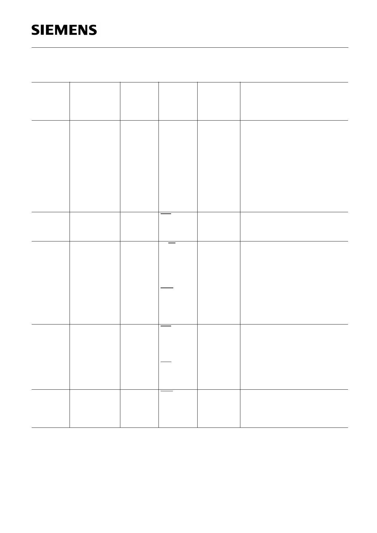
Pin Definitions and Functions
Pin No. Pin No.
Pin No. Symbol
P-DIP-40 P-MQFP-64 P-LCC-44
37
37
38
38
39
39
40
40
1
41
2
42
3
43
4
44
41
AD0/D0
42
AD1/D1
43
AD2/D2
44
AD3/D3
1
AD4/D4
2
AD5/D5
3
AD6/D6
4
AD7/D7
34
27
37
CS
‚Äď
28
38
R/W
35
28
‚Äď
29
36
29
20
8
38
WR
39
DS
39
RD
23
INT
Input (I) Function
Output (O)
Open
Drain (OD)
I/O
Multiplexed Bus Mode:
I/O
Address/data bus transfers
I/O
addresses from the ¬ĶP system
I/O
to the ISAC-S TE and data
I/O
between the ¬ĶP system and
I/O
the ISAC-S TE.
I/O
Non-Multiplexed Bus Mode:
I/O
Data bus. Transfers data
between the ¬ĶP system and
the ISAC-S TE.
I
Chip Select: A “Low“ on this
line selects the ISAC-S TE for
a read/write operation.
I
Read/Write: When ‚ÄúHigh‚ÄĚ
identifies a valid ¬ĶP access as
a read operation. When ‚ÄúLow‚ÄĚ,
identifies a valid ¬ĶP access as
a write operation (Motorola
I
bus mode).
Write: This signal indicates a
write operation (Intel bus
mode).
I
Data Strobe: The rising edge
marks the end of a valid read
or write operation (Motorola
bus mode).
I
Read: This signal indicates a
read operation (Intel bus
mode).
OD
Interrupt Request: The signal
is activated when the ISAC-S
TE requests an interrupt. It is
an open drain output.
Semiconductor Group
11
Share Link: 