RT8280 データシートの表示(PDF) - Richtek Technology
部品番号
コンポーネント説明
メーカー
RT8280 Datasheet PDF : 16 Pages
| |||
RT8280
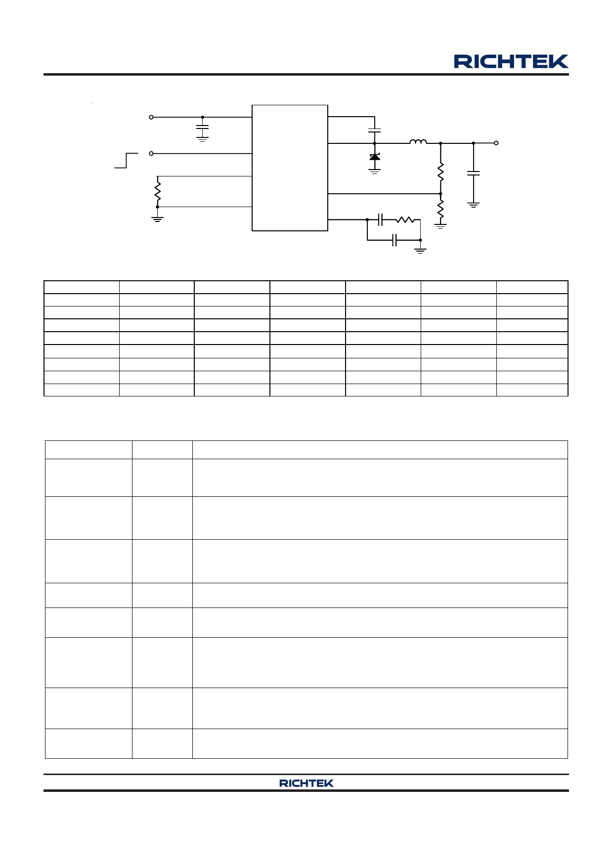
Typical Application Circuit
VIN
4.5V to 24V
Chip Enable
CIN
10µF
2 VIN
BOOT 1
7 EN
RT8280
SW 3
8 RT
RRT
24k
4,
9 (Exposed Pad)
GND
FB 5
COMP 6
CBOOT L
10nF 2.2µH
B330A
R1
31.6k
VOUT
3.3V/3A
COUT
22µF
CC
1.8nF
RC
24k
R2
10k
VOUT (V)
10
8
5
3.3
2.5
1.8
1.5
1.2
NCCP
Table 1. Recommended Component Selection for fSW = 2.2MHz
R1 (kΩ)
115
R2 (kΩ)
10
RC (kΩ)
68
CC (nF)
0.82
L (μH)
8.2
91
10
51
1
6.8
5 2.3
10
36
1.2
4.7
3 1.6
10
24
1.8
2.2
2 1.5
10
18
2.2
2
1 2.4
10
13
2.2
1.5
8 .87
10
12
2.2
1.5
4 .99
10
9
1.8
1
COUT (μF)
22
22
22
22
22
22
22
22
Functional Pin Description
Pin No.
1
2
Pin Name
BOOT
VIN
Pin Function
Bootstrap Power. BOOT supplies the drive for the high side N-MOSFET switch.
Connect a 10nF or greater capacitor from SW to BOOT to power the high side
switch.
Supply Input. VIN supplies the power to the IC, as well as the step-down
converter switches. Drive VIN with a 4.5V to 24V power source. Bypass VIN to
GND with a suitably large capacitor to eliminate noise on the input to the IC.
3
SW
4,
9 (Exposed Pad)
GND
5
FB
6
COMP
7
EN
8
RT
Switch Node. SW is the switching node that supplies power to the output.
Connect the output LC filter from SW to the output load. Note that a capacitor is
required from SW to BOOT to power the high side switch.
Ground. The exposed pad must be soldered to a large PCB and connected to
GND for maximum power dissipation.
Feedback Input. FB senses the output voltage to regulate. Drive FB with a
resistive voltage divider from the output voltage.
Compensation Node. COMP is used to compensate the regulation control loop.
Connect a series RC network from COMP to GND to compensate the regulation
control loop. In some cases, an additional capacitor from COMP to GND is
required.
Enable Input. EN is a digital input that turns the regulator on or off. Drive EN
higher than 1.4V to turn on the regulator, lower than 0.4V to turn off. For
automatic startup, leave EN unconnected.
Oscillator Resistor Input. Connecting a resistor to ground from this pin sets the
switching frequency.
Copyright ©2012 Richtek Technology Corporation. All rights reserved.
www.richtek.com
2
is a registered trademark of Richtek Technology Corporation.
DS8280-02 March 2012
Share Link: 