RT9204 データシートの表示(PDF) - Richtek Technology
部品番号
コンポーネント説明
メーカー
RT9204 Datasheet PDF : 14 Pages
| |||
RT9204/A
Preliminary
COUNT = 1 COUNT = 2 COUNT = 3
4V
2V
0V
OVERLOAD
APPLIED
Shutdown
Pulling high the SD pin by a small single transistor can
shutdown the RT9204/A PWM controller as shown in
typical application circuit. Normally SD pin can be floating
because an internal 40µA current source will pull low
the SD shutdown pin voltage.
L
Q
T0T1
T2
T3
TIME
Figure 5
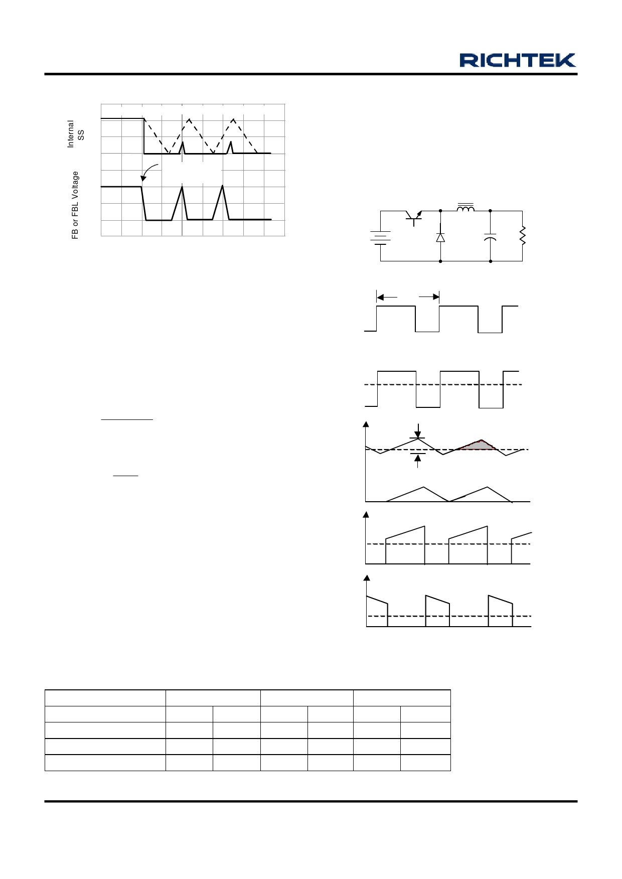
Inductor Selection
The RT9204/A was designed for VIN = 5V, step-down
application mainly. Figure 6 shows the typical topology
and waveforms of step-down converter.
The ripple current of inductor can be calculated as follows:
(5V - VOUT)
ILRIPPLE =
× TON
L
Because operation frequency is fixed at 600kHz,
VOUT
TON = 3.33 ×
5V
The VOUT ripple is
VOUT RIPPLE = ILRIPPLE × ESR
ESR is COUT capacitor equivalent series resistor
Table 1 shows the ripple voltage of VOUT: VIN = 5V
*Refer to Sanyo low ESR series (CE, DX, PX......)
The suggested L and C are as follows:
2µH with ≥ 1500µF COUT
5µH with ≥ 1000µF COUT
VI
D
C
R VO
C.C.M.
TS
Table 1
TON TOFF
VI - VO
VL
- VO
iL
uQ
uIL
IL = IO
iQ
IQ
iD
ID
Figure 6
VOUT
Inductor
1000µF (ESR = 53mΩ)
1500µF (ESR = 33mΩ)
3000µF (ESR = 21mΩ)
3.3V
2µH
5µH
100mV 40mV
62mV 25mV
40mV 16mV
2.5V
2µH
5µH
110mV 44mV
68mV 28mV
43mV 18mV
1.5V
2µH
5µH
93mV 37mV
58mV 23mV
37mV 15mV
www.richtek.com
10
DS9204/A-08 March 2007
Share Link: 