RT9501A データシートの表示(PDF) - Richtek Technology
部品番号
コンポーネント説明
メーカー
RT9501A Datasheet PDF : 9 Pages
| |||
Preliminary
RT9501A/B
Constant Voltage Regulation and Charge
Termination Mode
When the battery voltage reaches the regulation voltage
VO(REG), the constant voltage feedback control starts, and
then the charge current begins to decrease as the typical
charge profile shown. As the charge current decreases
to lower than charge terminated current threshold, the
RT9501 will terminate the charge cycle.
Recharge Mode
After the charge termination mode, if the battery voltage
falls to lower than the recharge threshold voltage VO(RCH),
the RT9501 will begin a new charge cycle according to
the battery voltage.
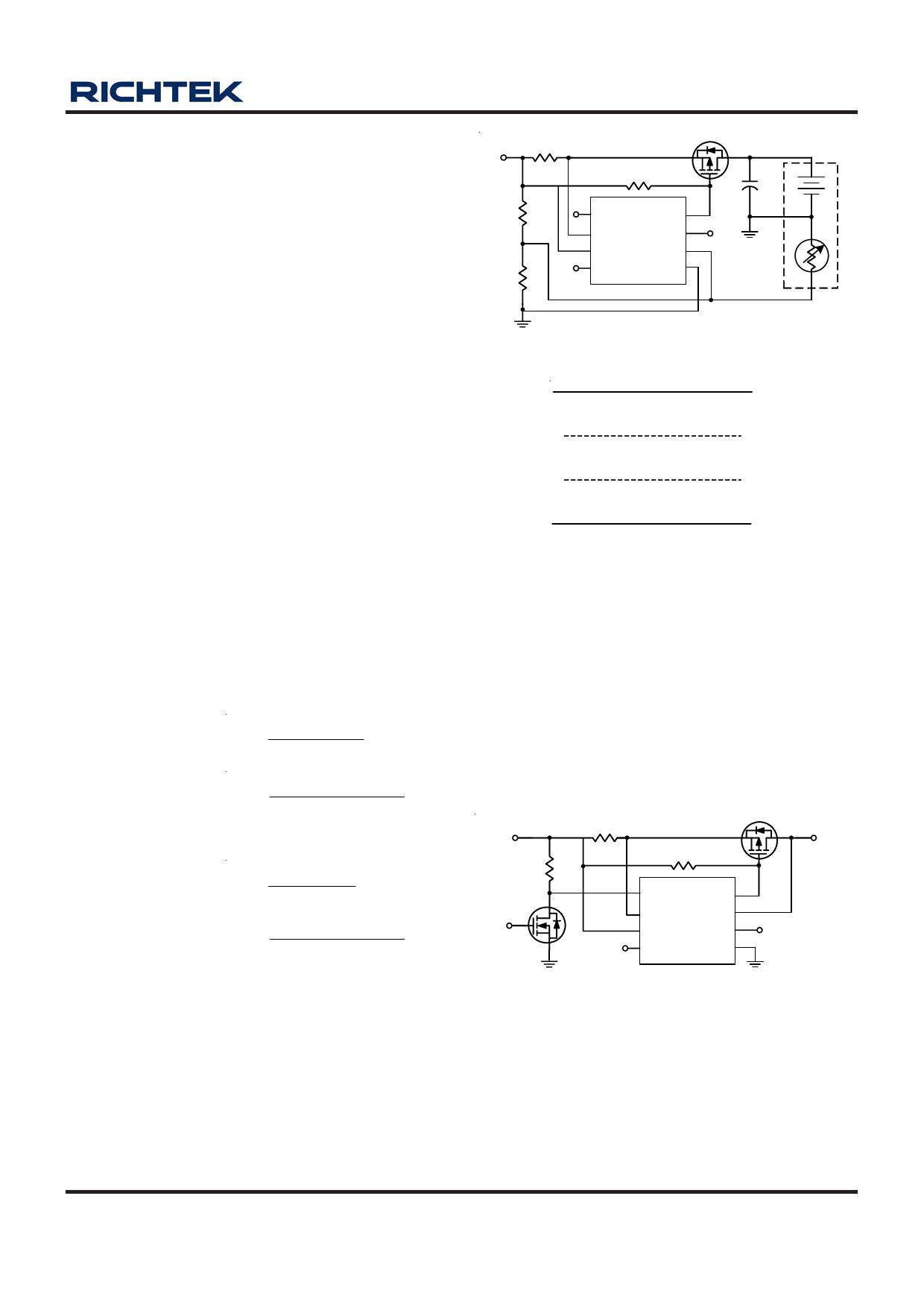
Battery Temperature Detection
The RT9501 continuously detects the battery temperature
by measuring the TS pin voltage. A NTC or PTC
thermistor can parallel with RT2 to deviate the TS pin
voltage. (As shown in Figure 5) The TS pin voltage must
be within normal temperature voltage range that is shown
in Figure 6 and electrical characteristics, and then RT9501
can start working normally.
The RT1 and RT2 can be derived from following equations.
For NTC Thermistors:
5 × RTH × RTL
RT1 =
3 × (RTL - RTH)
5 × RTH × RTL
RT2 =
[(2 × RTL) - (7 × RTH)]
For PTC Thermistors:
5 × RTH × RTL
RT1 =
3(RTH - RTL)
5 × RTH × RTL
RT2 =
[(2 × RTH) - (7 × RTL)]
Where RTL is the resistance value in lowest desired
operation temperature and RTH is the resistance value in
highest desired operation temperature. The resistances
of thermistors are specified by the thermistor
manufacturer. If the temperature monitoring function is
not desired, there's an easy method to set RT1 and RT2 at
the same value and disconnect the thermistor to disable
this function.
RCS
VIN
RT1
RT2
Q1
R4
FB/CE
CS
VDD
STAT
CC
BATT
TS
GND
Figure 5
Battery
Pack
+
C2
Thermistor
VDD
Temperature Fault Range
VTS2
Normal Temperature Range
VTS1
Temperature Fault Range
GND
Figure 6
FB/CE Pin Functions
This pin has two functions, one is to enable/disable the
charge function, and the other is to finely adjust battery
regulation voltage. Connect this pin to VDD to enable
RT9501, and connect to ground to disable it (Figure 7). If
this pin is connected to a voltage divider as shown in
Figure 8, it can be a 2.1V reference voltage to adjust the
output regulation voltage as desired.
VIN
RCE
GPIO
RCS
Q1
R4
CE
CS
VDD
STAT
CC
BATT
TS
GND
Battery
Figure 7. For CE pin Function
DS9501A/B-07 March 2007
www.richtek.com
7
Share Link: 