SAA7207H/C1 データシートの表示(PDF) - Philips Electronics
部品番号
コンポーネント説明
メーカー
SAA7207H/C1 Datasheet PDF : 20 Pages
| |||
Philips Semiconductors
Reed Solomon decoder IC
Product specification
SAA7207H
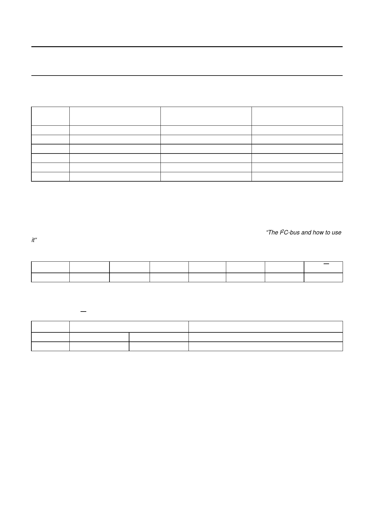
Mode of operation
Table 2 Mode of operation for boundary scan test
PIN
TC0
TC1
TRST
TMS
TCK
TDI
INTERNAL CONNECTION
pull-down
pull-down
pull-up
pull-up
none
pull-up
APPLICATION MODE
(REED SOLOMON)
logic 0 or open-circuit
logic 0 or open-circuit
logic 0(1)
open-circuit
open-circuit
open-circuit
BOUNDARY SCAN TEST
logic 0 or open-circuit
logic 0 or open-circuit
logic 1 or open-circuit
input
input
input
Note
1. The safest way to deactivate the Boundary Scan Test (BST) circuitry is to set TRST to logic 0.
Control, monitoring and extension port interface
An I2C-bus slave transmitter interface is included to provide the possibilities for a host to send control data and/or read
monitoring information. For details of the interface protocol and timing on the I2C-bus see “The I2C-bus and how to use
it”; 12NC number 9398 393 40011.
Table 3 Slave address
A6
A5
A4
A3
A2
A1
A0
R/W
1
1
0
1
0
0
1
X(1)
Note
1. When X = 1 = read; when X = 0 = write.
Table 4 Write (R/W = 0)
BYTE
1st byte
2nd byte(2)
LOGIC LEVEL
0
0
ERF(3)
0
DESCRIPTION(1)
output data Port 5 to Port 0
mode control Port 5 to Port 0
Notes
1. Output data bits for port 5 to port 0; mode control bits for Port 5 to Port 0 (1 = input, 0 = output).
2. Sending the 2nd byte will force the IC to reset.
3. When ERF = 1 the error flag is set for uncorrectable blocks; when ERF = 0 the error flag is always left unmodified;
default: ERF = 1, mode control = 111111 (default = default value after a hardware reset).
1996 Jul 17
8
Share Link: 