SC1531 データシートの表示(PDF) - Semtech Corporation
部品番号
コンポーネント説明
メーカー
SC1531 Datasheet PDF : 11 Pages
| |||
POWER MANAGEMENT
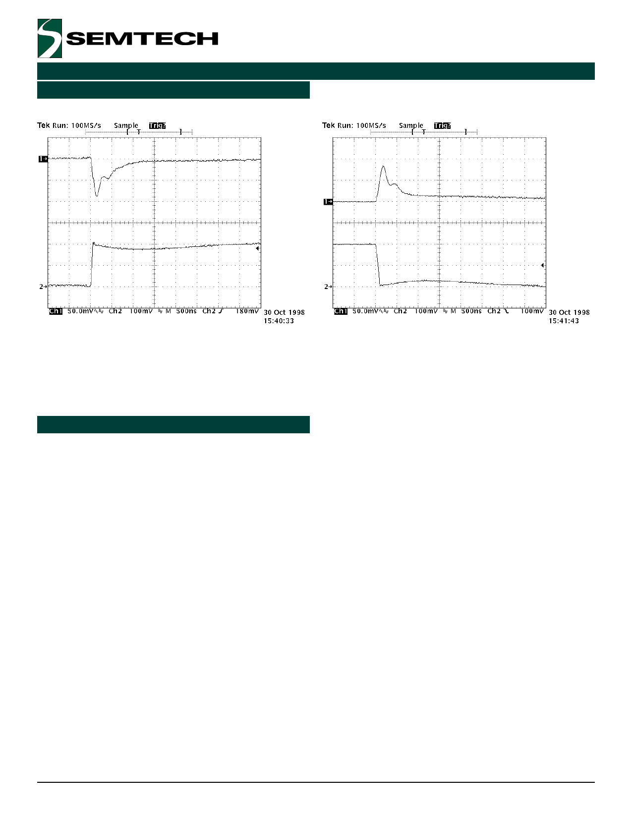
Typical Characteristics (Cont.)(1)
Load Transient Response
SC1531(A)
Load Transient Response
Trace 1: VO
Trace 2: IO stepping from 0mA to 200mA
Notes:
(1) In Application Circuit on page 1.
(2) IO = 200mA.
Applications Information
Introduction
Trace 1: VO
Trace 2: IO stepping from 200mA to 0mA
The SC1531(A) is intended for applications such as power
managed PCI and network interface cards (NICs), where
operation from a 3.3V VAUX supply may be required when
the 5V supply has been shut down. It provides a very
simple, low cost solution that uses very little pcb real
estate. During regular operation, 3.3V power for the PCI
card is provided by the SC1531(A)s on-board low
dropout regulator, generated from the 5V supply. When
the 5V supply is removed and 3.3V VAUX is available, the
SC1531(A) connects this supply directly to its output
using a tiny SOT-23 external p-channel FET. Connection
of pin 3 (VAUX) to the 3.3V supply is optional, and adds
active pull-down to the Drive pin.
target is easily met using surface mount ceramic or
tantalum capacitors.
Input capacitors (5V) - Semtech recommends the use of
a 4.7µF ceramic or tantalum capacitor plus a 0.1µF
ceramic capacitor at the input. This allows for the device
being some distance from any bulk capacitance on the
rail. Additionally, input droop due to load transients is
reduced, improving load transient response.
Input capacitors (3.3V) - Semtech recommends
decoupling this pin (if used) with a 0.1µF ceramic
capacitor.
Component Selection
Output capacitors - Semtech recommends a minimum
bulk capacitance of 4.7µF at the output, along with a
0.1µF ceramic decoupling capacitor. Increasing the bulk
capacitance will improve the overall transient response.
The device is very tolerant of capacitor value and ESR
variations, in fact, any combination of capacitors with
C ³ 4.7µF and ESR < 1W is sufficient for stability. This
P-channel bypass FET - selection of the external FET is
determined by two main requirements:
1) the FET has to have a very low gate threshold
(typically ~1V) in order to be sufficiently turned on with
VGS £ 3.3V.
2) the FET RDS(ON) must be low enough such that:
( ) VAUX − IO (MAX ) • R DS ( ON ) ≥ VO (MIN )
ã 2000 Semtech Corp.
8
www.semtech.com
Share Link: 