SG140-18L データシートの表示(PDF) - Microsemi Corporation
部品番号
コンポーネント説明
メーカー
SG140-18L Datasheet PDF : 9 Pages
| |||
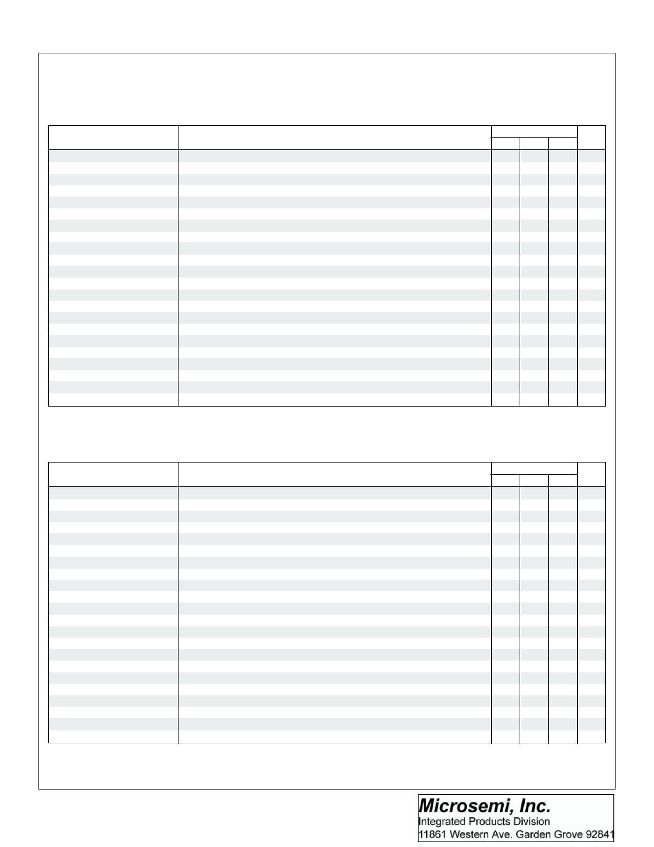
SG140A/SG140 SERIES
15V POSITIVE REGULATOR
ELECTRICAL CHARACTERISTICS (Note 1)
SG140 A - 15
(Unless otherwise specified, these specifications apply over full operating ambient temperatures for SG140A -15 with -55°C ≤ TA ≤ 150°C, and
VIN = 23V, IO = 1.0A, CIN = 0. 33µF, COUT = 0.1µF and are applicable for the K, R, and IG - Power package - only. Low duty cycle pulse testing techniques
are used which maintains junction and case temperature equal to the ambient temperature.)
Parameter
Output Voltage
Line Regulation (Note 1)
Load Regulation (Note 1)
Total Output Voltage
Tolerance
Quiescent Current
Quiescent Current Change
Dropout Voltage
Peak Output Current
Short Circuit Current
Ripple Rejection
Output Noise Voltage (rms)
Long Term Stability
Thermal Shutdown
Test Conditions
I = 5mA to 1.0A, T = 25°C
O
J
VIN = 17.9V to 30V, IO = 500mA
V = 7.5V to 30V, T = 25°C
IN
J
VIN = 20V to 26V
V = 20V to 26V, T = 25°C
IN
J
IO = 5mA to 1.0A
IO = 5mA to 1.5A, TJ = 25°C
IO = 250mA to 750mA, TJ = 25°C
VIN = 17.9V to 30V, IO = 5mA to 1.0A, P ≤ 15W
Over Temperature Range
TJ = 25°C
With Line: VIN = 17.9V to 30V, IO = 500mA
V = 17.9V to 30V, I = 1A, T = 25°C
IN
O
J
With Load: IO = 5mA to 1.0A
∆VO
=
100mV,
I
O
=
1A,
T
J
=
25°C
TJ = 25°C
T = 25°C
J
∆VIN = 10V, f = 120Hz, TJ = 25°C
f = 10Hz to 100KHz (Note 2)
1000hrs. at TJ = 125°C
IO = 5mA
SG140A - 15
Min. Typ. Max.
Units
14.7 15.0 15.3 V
22 mV
22 mV
30 mV
10 mV
75 mV
35 mV
21 mV
14.4 15.0 15.6 V
6.5 mA
6 mA
0.8 mA
0.8 mA
0.5 mA
2 2.5 V
2.4
A
2.1
A
60
dB
40 µV/V
60
mV
175
°C
SG140 - 15
(Unless otherwise specified, these specifications apply over full operating ambient temperatures for SG140-15 with -55°C ≤ TA ≤ 150°C, and VIN = 23V,
IO = 500mA, CIN = 0. 33µF, COUT = 0.1µF and are applicable for the K, R, and IG - Power package - only. Low duty cycle pulse testing techniques are
used which maintains junction and case temperature equal to the ambient temperature.)
Parameter
Test Conditions
SG140 - 15
Min. Typ. Max.
Units
Output Voltage
Line Regulation (Note 1)
Load Regulation (Note 1)
Total Output Voltage
Tolerance
Quiescent Current
Quiescent Current Change
Dropout Voltage
Peak Output Current
Short Circuit Current
Ripple Rejection
Output Noise Voltage (rms)
Long Term Stability
Thermal Shutdown
IO = 5mA to 1.0A, TJ = 25°C
V = 18.5V to 30V
IN
VIN = 17.5V to 30V, TJ = 25°C
V = 20V to 26V, I = 1.0A
IN
O
VIN = 17.7V to 30V, IO = 1.0A, TJ = 25°C
IO = 5mA to 1.0A
IO = 5mA to 1.5A, TJ = 25°C
IO = 250mA to 750mA, TJ = 25°C
VIN = 17.5V to 30V, IO = 5mA to 1.0A, P ≤ 15W
IO = 1.0A
TJ = 25°C
With Line: V = 18.5V to 30V
IN
VIN = 18.5V to 30V, IO = 1A, TJ = 25°C
With Load: I = 5mA to 1.0A
O
∆VO = 100mV, IO = 1A, TJ = 25°C
T = 25°C
J
TJ = 25°C
∆VIN = 10V, f = 120Hz, TJ = 25°C
f = 10Hz to 100KHz (Note 2)
1000hrs. at TJ = 125°C
IO = 5mA
14.4 15.0 15.6 V
150 mV
150 mV
75 mV
150 mV
150 mV
150 mV
75 mV
14.25 15.00 15.75 V
8.5 mA
8 mA
1.0 mA
1.0 mA
0.5 mA
2 2.5 V
2.4
A
2.1
A
54
dB
40 µV/V
60
mV
175
°C
Note 1. All regulation tests are made at constant junction temperature with low duty cycle testing.
2. This test is guaranteed but is not tested in production.
2/90 Rev 1.4 6/97
Copyright 1997
LINFINITY Microelectronics Inc.
11861 Western Avenue ∞ Garden Grove, CA 92841
7
(714) 898-8121 ∞FAX: (714) 893-2570
Share Link: 