SIP12501 データシートの表示(PDF) - Vishay Semiconductors
部品番号
コンポーネント説明
メーカー
SIP12501
Vishay Semiconductors

SIP12501 Datasheet PDF : 9 Pages
| |||
SiP12501
Vishay Siliconix
Product is End of Life 3/2014
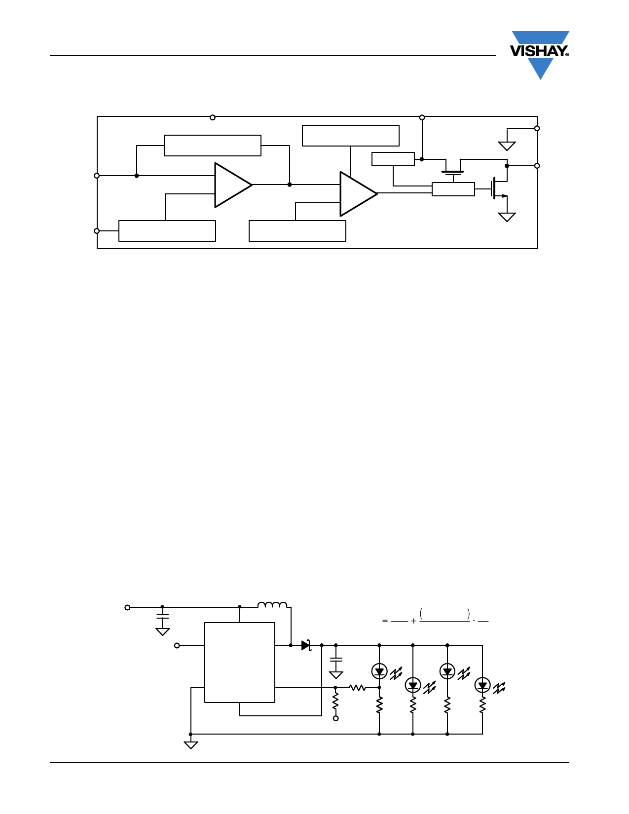
FUNCTIONAL BLOCK DIAGRAM
VOUT
Compensation
FB
-
E/A
+
VIN
Thermal Shutdown
Start-Up
Antiringing SW
+
PWM
-
Driver
GND
LX
XSHD
Reference and Soft-Start
Oscillator
DETAILED OPERATION
SiP12501 is a 600 kHz boost converter IC, packaged in 6 pin
MLP33, for white LED applications. With start-up from low
battery input voltage of 0.65 V, this device features fixed
frequency voltage mode PWM control with internal frequency
compensation. With its low rDS(on) internal power MOSFET,
this device maintains high efficiency over a wide range of
load current.
Low Voltage Start-Up
SiP12501 is designed to start-up at input voltage of typically
0.65 V. In the beginning, VOUT is lower than VIN because of
the voltage drop of the Schottky diode, the device uses VIN
as the power source for the start-up circuit and uses current
limit with fixed off-time to control the increase of the output
voltage. Once VOUT exceeds VIN, the device uses VOUT as
the power source. When VOUT exceeds 1.89 V, the device
switches to soft-start.
Soft-Start
During soft-start, the loop compensation guarantees the slow
increase of the output voltage and inrush current, so that no
large voltage overshoot and inrush current occur when the
soft-start is ended.
PWM operation
After soft-start, the device works in PWM operation with a
fixed frequency of 600 kHz.
Thermal Shutdown Protection
If the temperature of the device is above 160 °C, the device
will turn off the internal power MOSFET and wait until the
temperature drops below 140 °C, then the device goes into
the soft-start process again and finally the system recovers.
During thermal shutdown, the output voltage drops below
1.89 V minus UVLO hysteresis, start-up will be triggered to
keep the output voltage above 1.89 V.
Antiringing Control
The antiringing control circuitry prevents high frequency
ringing of the LX pin as the inductor current goes to zero by
damping the resonant circuit formed by L and CLX
(capacitance on LX pin). When the IC is shutdown, this
antiringing switch is also turned on.
APPLICATION INFORMATION
White LED Brightness Control
The current of white LED can be adjusted by a PWM signal
on XSHD or by a variable dc voltage to control its brightness.
(see Figure 1.) As control voltage VCTRL increases, the
voltage drop on R2 increases and the voltage drop on R1
decreases. Thus, the LED current decreases. The selection
of R2 and R3 will make the current from VCTRL much smaller
than LED current and much larger than the FB pin bias
current.
VIN
10 µF
XSHD
2
VIN
1
XSHD
10 µH
LX 6
SiP12501
5
XSHD
VOUT
3
FB 4
MBR0520
I LED
0.3 V
15 Ω
4.7 µF
R2
1 kΩ
R3
3.9 kΩ
VCTRL
R1
15 Ω
0.3 - VCTRL R2
15 Ω
R3
15 Ω
15 Ω
15 Ω
www.vishay.com
4
Document Number: 73192
S09-1455-Rev. B, 03-Aug-09
Share Link: