SIP12506DMP-TI-E3 データシートの表示(PDF) - Vishay Semiconductors
部品番号
コンポーネント説明
メーカー
SIP12506DMP-TI-E3 Datasheet PDF : 13 Pages
| |||
Product is End of Life 3/2014
SiP12506
Vishay Siliconix
WHITE LED BRIGHTNESS CONTROL
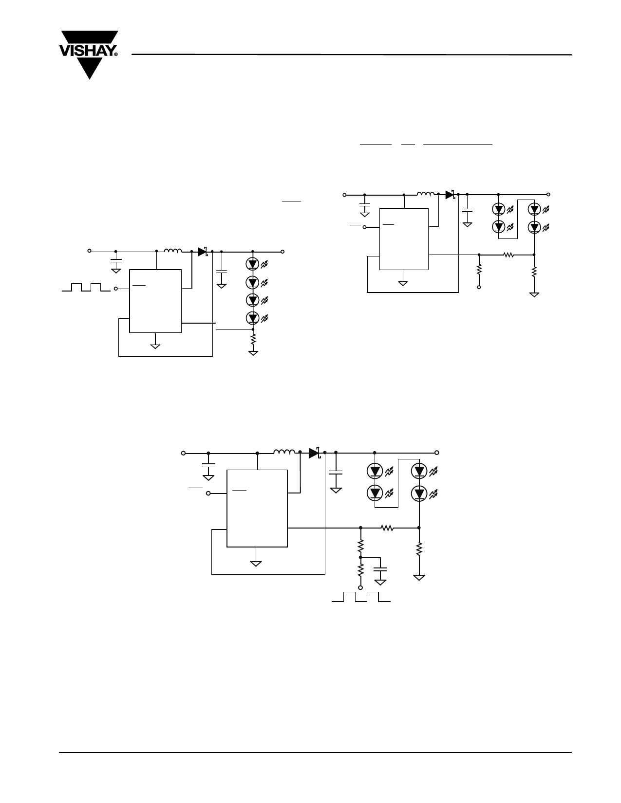
Figures 8 and 9 delineate two possible brightness control
schemes. In Figure 8, a PWM signal is injected into the shut-
down pin. The average LED current is proportional to the
duty cycle of the PWM signal and thus, the brightness will
vary from low to high as the duty cycle of the PWM signal is
increased. The frequency of the PWM signal has to be low
enough to allow the part to undergo soft-start and fully power
up at each cycle. A frequency of 100 Hz to 500 Hz is, there-
fore, recommended. The magnitude of the PWM signal
should be higher than the maximum enable voltage of SHD
pin, in order to let the dimming control perform correctly.
MBR0530
VIN
1 µF
L
2 10 µH
VIN
VO
COUT
1 µF
3 SHD
1
LX
100 - 500 Hz
SiP12506
5 VOUT
FB 4
GND
0. 208 V
6
10.5 Ω
Figure 8. SiP12506 Driving Four LEDs
In Figure 9, a more analog approach to brightness control. As
the control voltage VCTRL is increased from 0 V, the voltage
drop across R2 and R3 increases driving voltage on node A
low thereby reducing current through the White LEDs and
dimming brightness. Reducing VCTRL to about 0 V, will turn
the LEDs fully on with 20 mA of current. The equation for the
LED current can be expressed as
I LED
=
0.208 V
+
15 Ω
R2
×
R3
(0.208 V - VCTRL)
15 Ω
VIN
4.7 µF
SHD
MBR0530
2
VIN
10 µH
3 SHD
1
LX
COUT
1 µF
SiP12506
5
VOUT
GND
4
FB
0.208 V
6
R2
10 KΩ
R3
20 KΩ
VOUT
A
R1
15 Ω
VCTRL
Figure 9. White LED driver with adjustable brightness
Figure 10 demonstrates a more practical approach for dim-
ming control which is really the synthesis of the two ideas
demonstrated above. In this approach, a filtered PWM signal
acts as a DC voltage to control the brightness of the LEDs. It
is recommended that PWM signal with frequency higher than
22 kHz be used. Figures 11 and 12 illustrate other variations
of the previously mentioned ideas.
VIN
4.7 µF
SHD
MBR0530
2
VIN
10 µH
3 SHD
1
LX
COUT
1 µF
SiP12506
5 VOUT
GND
4
FB
0.208 V
6
R3
20 KΩ
R DC
100 KΩ
R2
10 KΩ
C DC
0.1 µF
VOUT
A
R1
15 Ω
PWM > 22 kHz
Figure 10. White LED driver with adjustable brightness control using a filtered PWM signal
Document Number: 73861
S-70547–Rev. D, 26-Mar-07
www.vishay.com
9
Share Link: 