AD7628 データシートの表示(PDF) - Analog Devices
部品番号
コンポーネント説明
メーカー
AD7628 Datasheet PDF : 8 Pages
| |||
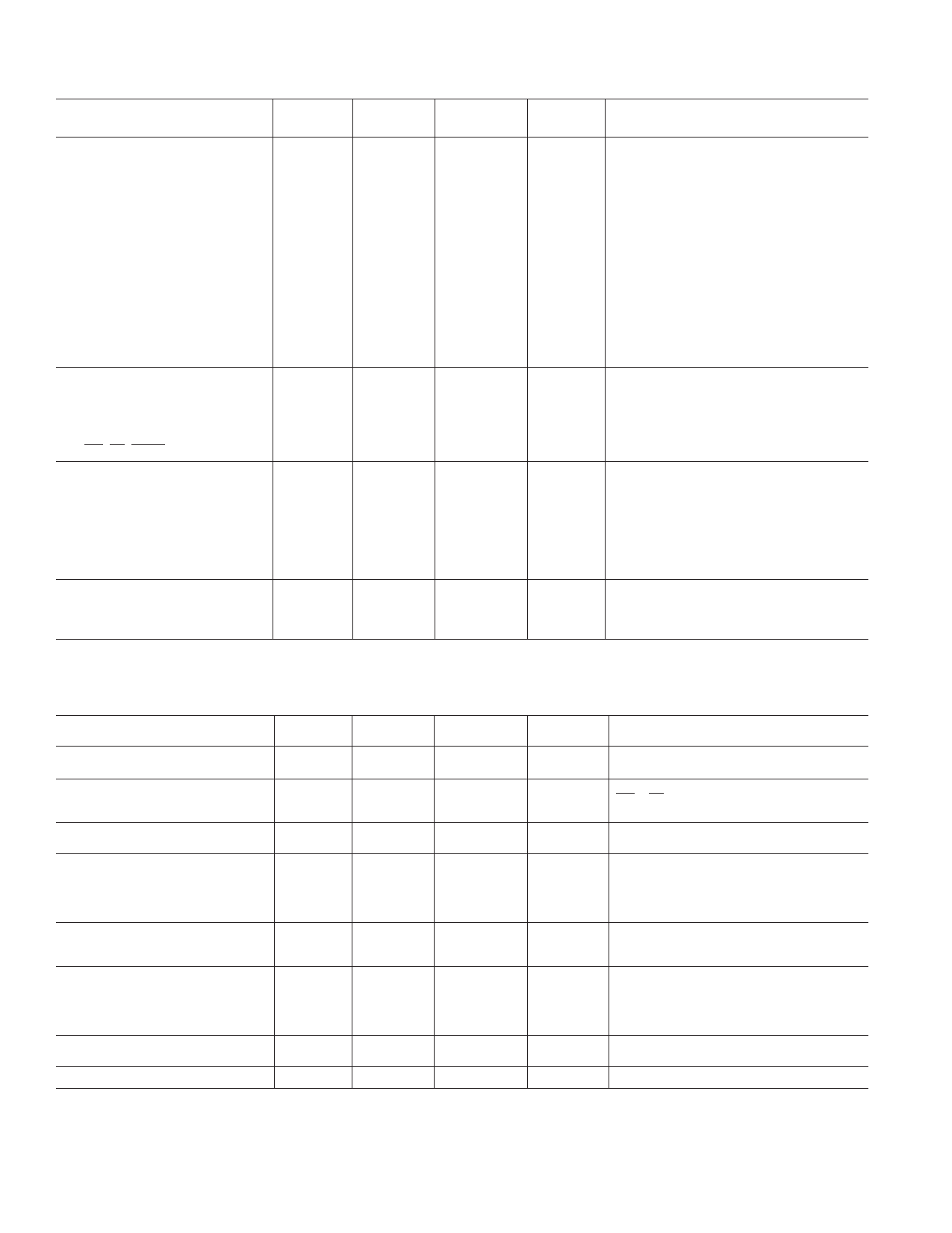
AD7628–SPECIFICATIONS (VDD = +10.8 V to +15.75 V, VREF A = VREF B = +10 V; OUT A = OUT B = 0 V unless
otherwise noted)
Parameter
STATIC PERFORMANCE2
Resolution
Relative Accuracy
Differential Nonlinearity
Gain Error
TA = +25؇C1
TA = –40؇C
to +85؇C
8
8
± 1/2
± 1/2
±1
±1
±2
±3
Gain Temperature Coefficient3
∆Gain/∆Temperature
Output Leakage Current
OUT A (Pin 2)
± 50
OUT B (Pin 20)
± 50
Input Resistance (VREFA, VREFB)
8
15
VREFA/VREFB Input Resistance
Match
±1
DIGITAL INPUTS4
Input High Voltage (VIH)
2.4
Input Low Voltage (VIL)
0.8
Input Current (IIN)
±1
Input Capacitance
DB0–DB7
10
WR, CS, DACA/DACB
15
SWITCHING CHARACTERISTICS3
See Timing Diagram
Chip Select to Write Set Up Time (tCS) 160
Chip Select to Write Hold Time (tCH) 10
DAC Select to Write Set Up Time (tAS) 160
DAC Select to Write Hold Time (tAH) 10
Data Valid to Write Set Up Time (tDS) 160
Data Valid to Write Hold Time (tDH) 10
Write Pulse Width (tWR)
150
POWER SUPPLY
IDD, K Grade
2
B, T Grades
2
All Grades
100
± 0.0035
± 200
± 200
8
15
±1
2.4
0.8
± 10
10
15
160
10
160
10
160
10
170
2
2.5
500
TA = –55؇C
to +125؇C1
8
± 1/2
±l
±3
± 0.0035
± 200
± 200
8
15
±1
2.4
0.8
± 10
10
15
Units
Test Conditions/Comments
Bits
LSB max
LSB max
LSB max
%/°C max
nA max
nA max
kΩ min
kΩ max
% max
This is an Endpoint Linearity Specification
All Grades Guaranteed Monotonic Over
Full Operating Temperature Range
Measured Using Internal RFB A and RFB B.
Both DAC Latches Loaded with 11111111.
Gain Error is Adjustable Using Circuits
of Figures 4 and 5.
DAC Latches Loaded with 00000000
Input Resistance TC = –300 ppm/°C, Typical
Input Resistance is 11 kΩ
V min
V max
µA max
pF max
pF max
VIN = 0 or VDD
210
ns min
10
ns min
210
ns min
10
ns min
210
ns min
10
ns min
210
ns min
See Figure 3
mA
All Digital Inputs VIL or VIH
2.5
mA
All Digital Inputs VIL or VIH
500
µA
All Digital Inputs 0 V or VDD
Specifications subject to change without notice.
AC PERFORMANCE CHARACTERISTICS These characteristics are included for Design Guidance only and are not
subject to test. VDD = +10.8 V to +15.75 V. (Measured Using Recommended PC Board Layout (Figure 7) and AD644 as Output Amplifiers)
Parameter
DC SUPPLY REJECTION
(∆GAIN/∆VDD)
CURRENT SETTLING TIME
DIGITAL-TO-ANALOG GLITCH
IMPULSE
TA = +25؇C1
0.01
350
TA = –40؇C
to +85؇C1
0.02
400
330
TA = –55؇C
to +125؇πC1
0.02
400
Units
Test Conditions/Comments
% per % max ∆VDD = ± 5%
ns max
To 1/2 LSB OutA/OutB Load = 100 Ω.
WR = CS = 0 V.
DB0–DB7 = 0 V to VDD or VDD to 0 V
nV sec typ For Code Transition 00000000 to 11111111
OUTPUT CAPACITANCE
COUTA
COUTB
COUTA
COUTB
25
25
25
25
60
60
60
60
AC FEEDTHROUGH
VREFA to OUT A
VREFB to OUT B
–70
–65
–70
–65
CHANNEL-TO-CHANNEL ISOLATION
VREFA to OUT B
–80
VREFB to OUTA
–80
DIGITAL CROSSTALK
60
25
pF max
DAC Latches Loaded with 00000000
25
pF max
60
pF max
DAC Latches Loaded with 11111111
60
pF max
–65
dB max
VREFA, VREFB = 20 V p-p Sine Wave
–65
dB max
@ 10 kHz
dB typ
dB typ
nV sec typ
Both DAC Latches Loaded with 11111111.
VREFA = 20 V p-p Sine Wave @ 10 kHz
VREFB = 0 V See Figure 6.
VREFB = 20 V p-p Sine Wave @ 10 kHz
VREFA = 0 V See Figure 6.
Measured for Code Transition 00000000
to 11111111
HARMONIC DISTORTION
–85
dB typ
VIN = 6 V rms @ 1 kHz
NOTES
1Temperature Ranges are K Version; –40°C to +85°C; B Version; –40°C to +85°C; T Version; –55°C to +125°C.
2Specification applies to both DACs in AD7628.
3Guaranteed by design but not production tested.
4Logic inputs are MOS Gates. Typical input current (+25°C) is less than 1 nA.
Specifications subject to change without notice.
–2–
REV. A
Share Link: 