LA9242M データシートの表示(PDF) - SANYO -> Panasonic
部品番号
コンポーネント説明
メーカー
LA9242M Datasheet PDF : 20 Pages
| |||
LA9242M
6. Sled servo
The response characteristics are set by SLEQ (pin 28). The amplifier positioned after SLEQ (pin 28) has a mute
function that is applied when the SLED OFF command is issued. The sled is moved by inputting current to SL–
(pin 30) and SL+ (pin 31) ; specifically, the pins are connected to the microprocessor output ports via resistors, and
the movement gain is set by the resistance value of that resistor. It is important to note that if there is a deviation in
the resistance values for SL– (pin 30) and SL+ (pin 31), an offset will arise in the SLD output.
7. Spindle servo
This configures the servo circuit, which maintains the linear velocity of the disc at a constant speed, along with the
DSP. This circuit accepts signals from the DSP through CV– (pin 39) and CV+ (pin 40) and sets the equalizer
characteristics through SP (pin 24), SP– (pin26), and SPD (pin 27), which are output to SPD (pin 27). The 12-cm
mode amplifier gain is set by the resistor connected between SPG (pin 25) and the reference voltage. In 8-cm
mode, this amplifier serves as an internal buffer, and SPG (pin 25) is ignored. Note that the gain setting is made for
8-cm mode first, and then 12-cm mode. If SPG (pin 25) is left open, the gain is forcibly set for 8-cm mode, regard-
less of whether 8-cm or 12-cm mode is in effect.
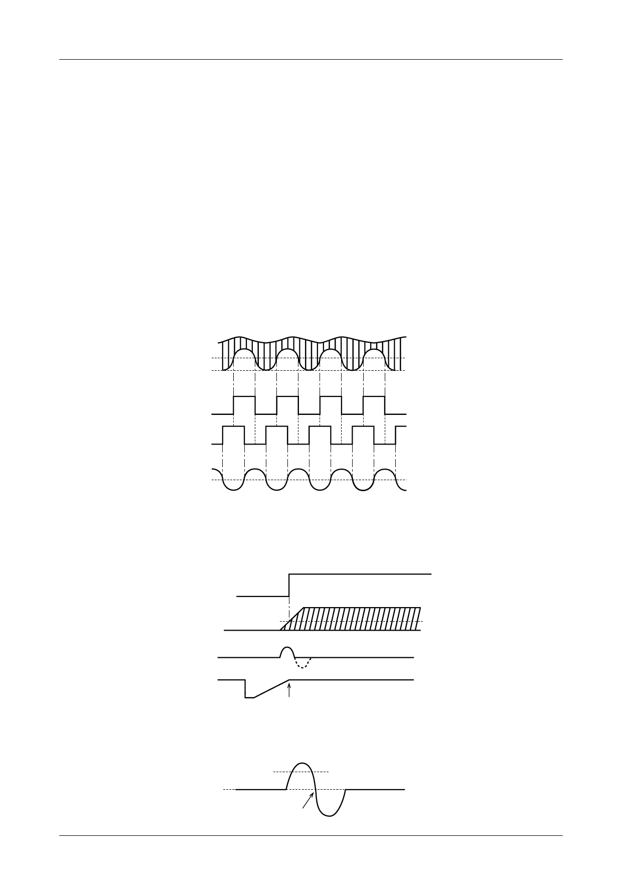
8. TES and HFL (traverse signals)
When moving the pickup from the outer track to the inner track, the EF output from the pickup must be connected
so that the phase relationship of TES and HFL is as shown in the diagram below. For the TESI input, the TES
comparator has negative polarity and hysteresis of approximately ±100mV. An external bandpass filter is needed in
order to extract only the required signal from the TE signal.
3.0V
RFSM
2.1V
1.5V
HFL
TES
TE
9. DRF (luminous energy determination)
DRF goes high when the peak of the EFM signal (RFSM output) held by the PH1 (pin 60) capacitor exceeds
approximately 2.3V. The PH1 (pin 60) capacitor affects the DRF detection time constant and the RFAGC response
bidirectional setting. The DRF output is driven by a constant current (250µA).
DRF
RFSM
3.0V
2.3V
1.5V
FE
Pickup position
Focus
10. Focus determination
Focus is assumed to be obtained when the focus error signal S curve reaching REF +0.2V is detected, and the S
curve subsequently returns to REF.
REF+0.2V
Focus
No.7097–8/20
Share Link: 