SP2526-2 データシートの表示(PDF) - Signal Processing Technologies
部品番号
コンポーネント説明
メーカー
SP2526-2 Datasheet PDF : 18 Pages
| |||
ABSOLUTE MAXIMUM RATINGS
These are stress ratings only and functional operation
of the device at these ratings or any other above those
indicated in the operation sections of the specifica-
tions below is not implied. Exposure to absolute maxi-
mum rating conditions for extended periods of time
may affect reliability.
Supply Voltage......................................-0.3V, +6.0V
Operating Temperature.....................-40˚C to +85˚C
Storage Temperature......................-65˚C to +150˚C
Power Dissipation Per Package
8-pin NSOIC
(derate 6.14mW/OC above+70OC).................500mW
8-pin PDIP
(derate 11.8mW/OC above+70OC)...............1000mW
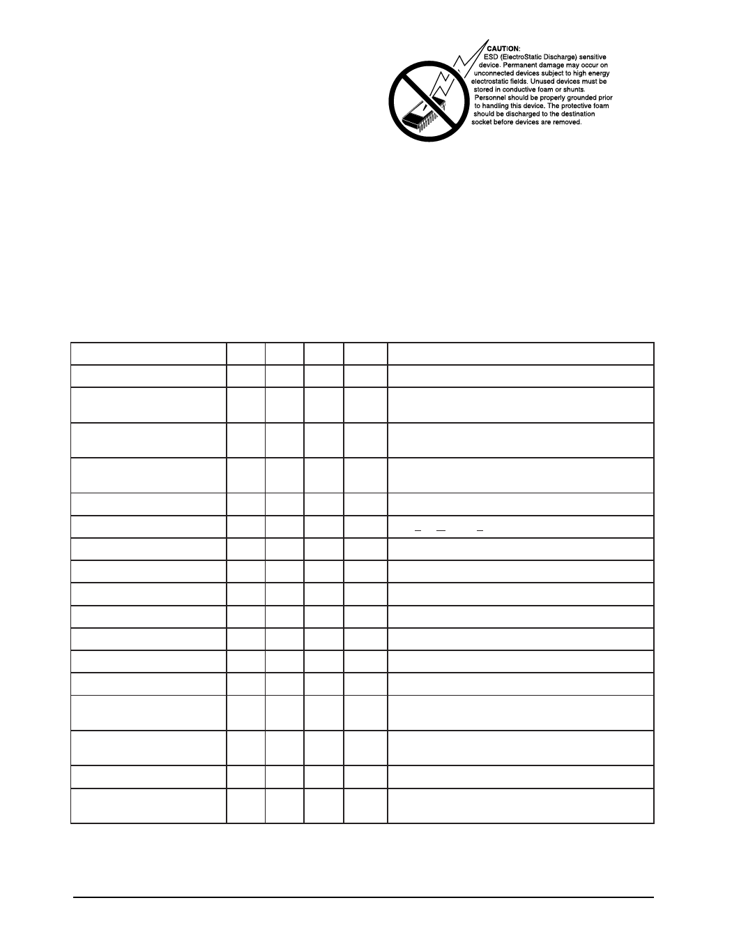
SPECIFICATIONS
Unless otherwise noted, the following specifications apply for VIN = +5.0V, TA = 25°C.
PARAMETER
MIN. TYP. MAX. UNITS
CONDITIONS
Operating Voltage Range, VIN
Supply Current, IIN
3.0
5.5
0.05 5.0
80 160
V
µA
enable off, no output load
enable on, no output load
Enable Input Threshold
Voltage
2.1 2.4
0.8 1.9
V
low to high transition
high to low transition
Enable Input Current
Enable Input Capacitance
0.01 1
0.01 1
1
µA
VEN = VOH(min) = 2.4V
VEN = VOL(max) = 0.8V
pF
Switch Resistance
Output Turn-On Delay
Output Turn-On Rise Time
Output Turn-Off Delay
Output Turn-Off Fall Time
Output Leakage Current
80
140
mΩ 3.3V<VIN < 5.0V,IL<500mA
0.5
ms RL=10Ω each output
1
ms RL=10Ω each output
1
20
µs RL=10Ω each output
1
20
µs RL=10Ω each output
.02 10
µA each output
Current Limit Threshold
2.0 2.8
A each output, Ramped load applied to enable output
Short-Circuit Current Limit
Over-Temperature Shutdown
Threshold
0.5 0.75 1.25
135
125
A each output, V = 0V
OUT
OC
increasing temperature
decreasing temperature
Error Flag Output Resistance
Error Flag Off Current
UVLO Threshold
10 25
15 40
0.01 1
2.7 3.0
2.5 2.6
Ω
V = 5V,I = 10mA
IN
L
VIN = 3.3V,IL = 10mA
µA
VFLAG = 5V
V
V increasing, T to T V decreasing T to T
IN
MIN
MAX , IN
, MIN
MAX
Rev. 8/21/01
SP2526 +3.0V to +5.5V USB Power Control Switch
2
© Copyright 2001 Sipex Corporation
Share Link: 