SP6659 データシートの表示(PDF) - Signal Processing Technologies
部品番号
コンポーネント説明
メーカー
SP6659 Datasheet PDF : 11 Pages
| |||
_____________________ SETTING THE
OUTPUT VOLTAGE
A resistive divider based on the following
equation determines the output voltage:
VOUT
=
0.6
(1+
R1
R2
)
The external resistive divider is connected
to the output as shown in Figure 20 .
APPLICATION INFORMATION
®
SP6659 VFB
GND
V OUT
R1
R2
Figure 20: Setting the SP6659 Output Voltage.
THEORY OF OPERATION
The SP6659 is a monolithic switching mode
Step-Down DC-DC converter. It utilizes in-
ternal MOSFETs to achieve high efficiency
and can generate very low output voltage
by using its internal reference at 0.6V. It
operates at a fixed switching frequency,
and uses slope compensated, current-mode
architecture. This Step-Down DC-DC con-
verter supplies 600mA of output current at
VIN = 3V. The entire input voltage range is
from 2.5V to 5.5V.
__________________ CURRENT MODE
PWM CONTROL
Slope compensated current mode PWM
control provides stable switching and cycle-
by-cycle current limit for excellent load and
line responses and protection of the internal
main switch (P-Channel MOSFET) as well
as the synchronous rectifier (N-Channel
MOSFET). During normal operation, the in-
ternal P-Channel MOSFET is turned on for
a certain time to ramp the inductor current at
each rising edge of the internal oscillator,
and switched off when the peak inductor
current is above the error voltage. The
current comparator, ICOMP, limits the peak
inductor current. When the main switch is
off, the synchronous rectifier will be turned
on immediately and stay on until either the
inductor current starts to reverse, as indi-
cated by the current reversal comparator,
IZERO, or the beginning of the next clock
cycle. The OVDET comparator controls
output transient overshoots by turning the
main switch off and keeping it off until the
fault is no longer present.
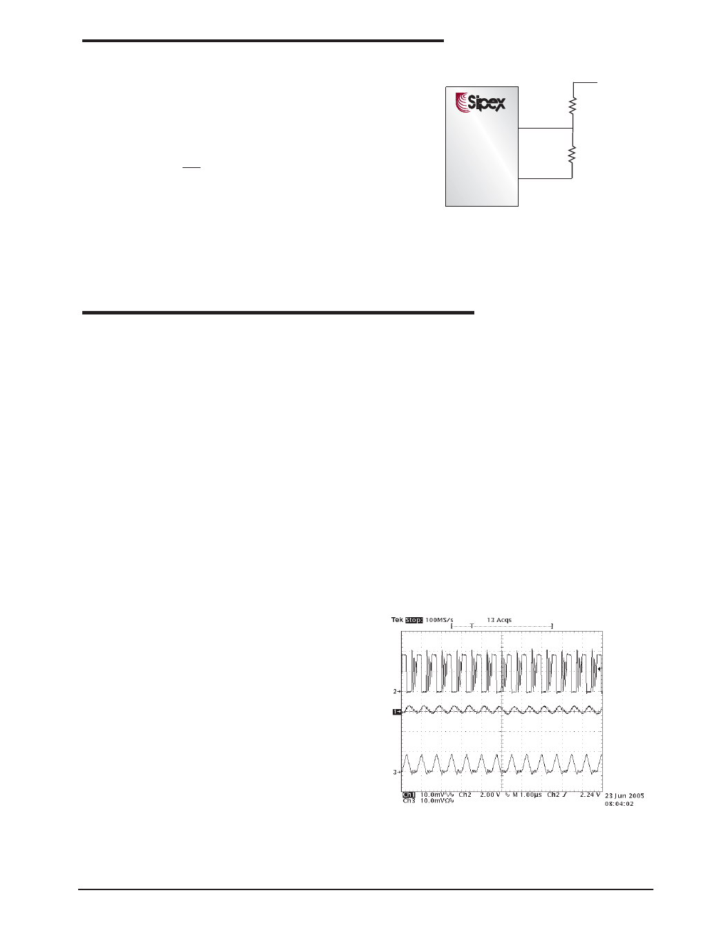
_______________________ IDLE MODE
OPERATION
At very light loads, the SP6659 automati-
cally enters Idle Mode (Figure 21).
Figure 21. SP6659 Idle Mode Operation
Date: 9/25/06 Rev C
SP6659 1.5MHz, 600mA Synchronous Buck Regulator
7
© 2006 Sipex Corporation
Share Link: 