BA3835F データシートの表示(PDF) - ROHM Semiconductor
部品番号
コンポーネント説明
メーカー
BA3835F Datasheet PDF : 10 Pages
| |||
Audio ICs
FOperation notes
(1) Frequency characteristics
The frequency characteristics of this IC are determined
by the resistor connected between the RREF terminal and
GND. For the specification conditions, the value of this
resistor is 100kΩ. If it is necessary to set the frequency
characteristics accurately, use a variable resistor (note :
all bands will shift together).
(2) Load characteristics
To convert the bias sense output signal to the GND sense
signal, the IC performs a V / I conversion, and then an
I / V conversion using a 10kΩ resistor (typ.) for the out-
put.
Therefore, if the load circuit connected to the A OUT pin
has a MOS structure there is no problem (eg. micropro-
cessor input port), but if the connected circuit has a low
input impedance, it may cause the output level to drop.
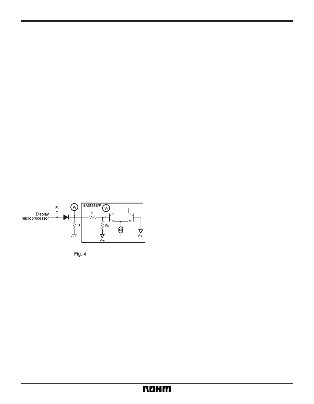
(3) External resistor for the control pin
When using a common port for the output select control
and FL drive, you must add a diode and resistor as shown
in Fig. 4 to prevent the FL drive “L” voltage from destroy-
ing the IC.
BA3835S / BA3835F
And from this, the following condition is obtained :
R < 30kΩ
In this case, the “L” level voltage V2 for the IC will
be :
V2 < 0.75V
(4) Recommended operating ranges
Provided that the IC is operated within the recommended
operating conditions and the recommended temperature
range, the basic circuit functions are guaranteed. Within
these ranges, ratings for electrical characteristics for
conditions other than those stipulated cannot be guaran-
teed, but the inherent function of the bandpass filter will
be maintained.
(5) Application circuit
Provided the recommended circuit constants are used,
the application circuit should function correctly. However,
we recommend that you confirm the characteristics of the
circuits in actual use and pay due attention to the caution-
ary notes given below.
If you change the circuit constants, check both the static
and transient characteristics of the circuit, and allow suffi-
cient margin to accommodate variations between both
ICs and external components. Note, also, that Rohm has
not been able to conduct a sufficient study into patent
rights.
In this case, the “L” voltage applied to the internal
comparator input terminal V1 is given by :
V1 =
R1)R
R1)R2)R
Vref
To maintain a noise margin of at least 2.5V with re-
spect to the comparator threshold level Vref, the rep-
resentative values for Vref, R1 and R2 are 1.5V, 20kΩ,
and 10kΩ respectively. This gives :
20kΩ)R
1.5V)0.25V<1.5V
20kΩ)10kΩ)R
608
Share Link: 