SST25PF020B データシートの表示(PDF) - Microchip Technology
部品番号
コンポーネント説明
メーカー
SST25PF020B Datasheet PDF : 33 Pages
| |||
SST25PF020B
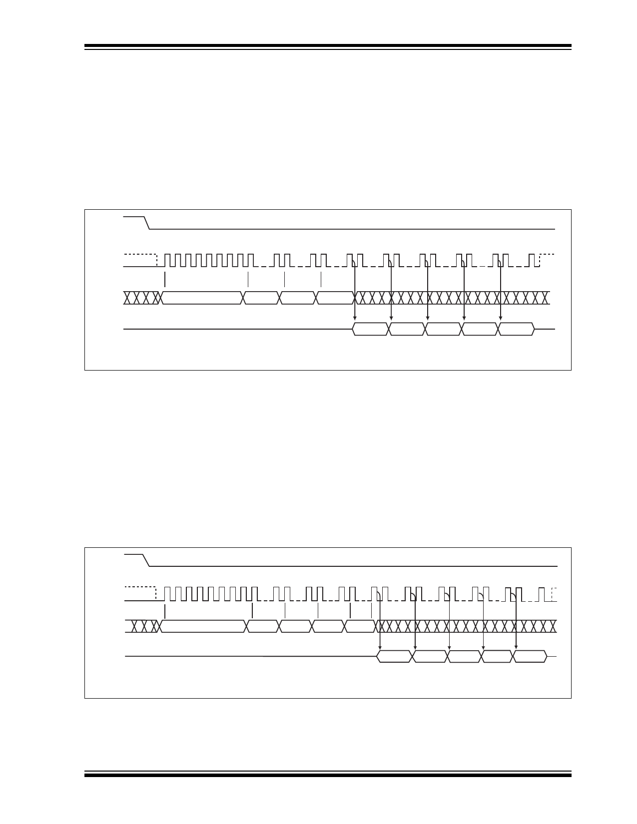
4.5.1 READ (33/25 MHZ)
The Read instruction, 03H, supports up to 33 MHz (2.7-
3.6V operation) or 25 MHz (2.3-2.7V operation) Read.
The device outputs the data starting from the specified
address location. The data output stream is continuous
through all addresses until terminated by a low to high
transition on CE#. The internal address pointer will
automatically increment until the highest memory
address is reached. Once the highest memory address
is reached, the address pointer will automatically incre-
ment to the beginning (wrap-around) of the address
space. Once the data from address location 3FFFFH
has been read, the next output will be from address
location 000000H.
The Read instruction is initiated by executing an 8-bit
command, 03H, followed by address bits [A23-A0]. CE#
must remain active low for the duration of the Read
cycle. See Figure 4-3 for the Read sequence.
CE#
MODE 3
SCK MODE 0
0 123456 78
15 16
23 24 31 32 39 40
47 48 55 56 63 64 70
SI
03
ADD. ADD. ADD.
MSB
MSB
HIGH IMPEDANCE
SO
N
DOUT
N+1
DOUT
N+2
DOUT
N+3
DOUT
N+4
DOUT
MSB
25135 ReadSeq.0
FIGURE 4-3:
READ SEQUENCE
4.5.2 HIGH-SPEED-READ (80/50 MHZ)
The High-Speed-Read instruction, supporting up to 80
MHz (2.7-3.6V operation) or 50 MHz (2.3-2.7V opera-
tion) Read, is initiated by executing an 8-bit command,
0BH, followed by address bits [A23-A0] and a dummy
byte. CE# must remain active low for the duration of the
High-Speed-Read cycle. See Figure 4-4 for the High-
Speed-Read sequence.
Following a dummy cycle, the High-Speed-Read
instruction outputs the data starting from the specified
address location. The data output stream is continuous
through all addresses until terminated by a low to high
transition on CE#. The internal address pointer will
automatically increment until the highest memory
address is reached. Once the highest memory address
is reached, the address pointer will automatically incre-
ment to the beginning (wrap-around) of the address
space. Once the data from address location 3FFFH
has been read, the next output will be from address
location 00000H.
CE#
MODE 3 0 1 2 3 4 5 6 7 8 15 16 23 24 31 32 39 40 47 48 55 56 63 64 71 72 80
SCK MODE 0
SI
0B
ADD. ADD. ADD.
X
MSB
MSB
SO
HIGH IMPEDANCE
N
DOUT
N+1
DOUT
N+2
DOUT
N+3
DOUT
N+4
DOUT
MSB
Note: X = Dummy Byte: 8 Clocks Input Dummy Cycle (VIL or VIH)
25135 HSRdSeq.0
FIGURE 4-4:
HIGH-SPEED-READ SEQUENCE
2013 Microchip Technology Inc.
DS20005135B-page 9
Share Link: 