ST62E62CD データシートの表示(PDF) - STMicroelectronics
部品番号
コンポーネント説明
メーカー
ST62E62CD
STMicroelectronics

ST62E62CD Datasheet PDF : 72 Pages
| |||
ST62T52CM-Auto ST62T62CM-Auto
1.2 PIN DESCRIPTIONS
VDD and VSS. Power is supplied to the MCU via
these two pins. VDD is the power connection and
VSS is the ground connection.
OSCin and OSCout. These pins are internally
connected to the on-chip oscillator circuit. A quartz
crystal, a ceramic resonator or an external clock
signal can be connected between these two pins.
The OSCin pin is the input pin, the OSCout pin is
the output pin.
RESET. The active-low RESET pin is used to re-
start the microcontroller.
TEST/VPP. The TEST must be held at VSS for nor-
mal operation. If TEST pin is connected to a
+12.5V level during the reset phase, the
EPROM/OTP programming Mode is entered.
NMI. The NMI pin provides the capability for asyn-
chronous interruption, by applying an external non
maskable interrupt to the MCU. The NMI input is
falling edge sensitive. It is provided with an on-chip
pullup resistor (if option has been enabled), and
Schmitt trigger characteristics.
PA4-PA5. These 2 lines are organized as one I/O
port (A). Each line may be configured under soft-
ware control as inputs with or without internal pull-
up resistors, interrupt generating inputs with pull-
up resistors, open-drain or push-pull outputs, ana-
log inputs for the A/D converter.
PB0, PB2-PB3, PB6-PB7. These 5 lines are or-
ganized as one I/O port (B). Each line may be con-
figured under software control as inputs with or
without internal pull-up resistors, interrupt generat-
ing inputs with pull-up resistors, open-drain or
push-pull outputs. PB6/ARTIMin and PB7/ARTI-
Mout are either Port B I/O bits or the Input and
Output pins of the ARTimer.
Reset state of PB2-PB3 pins can be defined by op-
tion either with pull-up or high impedance.
PB0, PB2-PB3, PB6-PB7 scan also sink 30mA for
direct LED driving.
PC2-PC3. These 2 lines are organized as one I/O
port (C). Each line may be configured under soft-
ware control as input with or without internal pull-
up resistor, interrupt generating input with pull-up
resistor, analog input for the A/D converter, open-
drain or push-pull output.
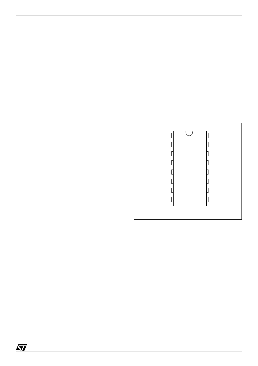
Figure 2. ST62T52C, E62C and T62C Pin
Configuration
PB0 1
VPP/TEST 2
PB2 3
PB3 4
ARTIMin/PB6 5
ARTIMout/PB7 6
VDD 7
VSS 8
16 PC2/Ain
15 PC3/Ain
14
NMI
13 RESET
12 OSCout
11 OSCin
10 PA5/Ain
9 PA4/Ain
5/72
Share Link: