STA518 データシートの表示(PDF) - STMicroelectronics
部品番号
コンポーネント説明
メーカー
STA518 Datasheet PDF : 19 Pages
| |||
STA518
Electrical specifications
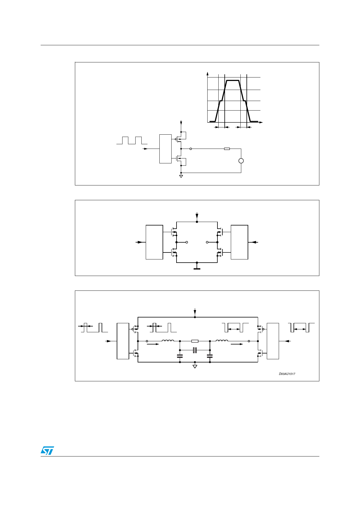
Figure 3. Low current dead time for Single End application: test circuit.
Low current dead time = MAX(DTr,DTf)
Duty cycle = 50%
INxY
+Vcc
M58
OUTxY
M57
gnd
OUTxY
Vcc
(3/4)Vcc
(1/2)Vcc
(1/4)Vcc
t
DTr
DTf
R 8Ω
+
-
V67 =
vdc = Vcc/2
D03AU1458
Figure 4. High current dead time for Bridge application: block diagram
+VCC
INxA
Q1
OUTxA
Q2
OUTxB
Q3
Q4
GND
D00AU1134
INxB
Figure 5. High current dead time for Bridge application: test circuit
High Current Dead time for Bridge application = ABS(DTout(A)-DTin(A))+ABS(DTOUT(B)-DTin(B))
+VCC
Duty cycle=A
DTin(A)
INA
DTout(A)
M58
Q1
Q2
M64
OUTA
Rload=8Ω
DTout(B)
OUTB
L67 22µ
Iout=4A
L68 22µ
Iout=4A
M57
Q3
C69
470nF
C71 470nF
C70
470nF
Q4
M63
Duty cycle=B
DTin(B)
INB
Duty cycle A and B: Fixed to have DC output current of 4A in the direction shown in figure
D03AU1517
11/19
Share Link: 