TA8428F データシートの表示(PDF) - Toshiba
部品番号
コンポーネント説明
メーカー
TA8428F Datasheet PDF : 14 Pages
| |||
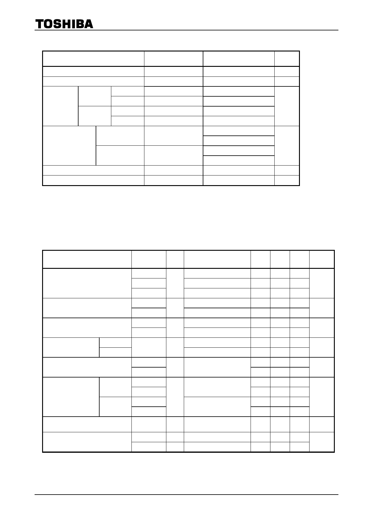
TA8428K(S)/F/FG
ABSOLUTE MAXIMUM RATINGS (Ta = 25°C)
CHARACTERISTIC
SYMBOL
RATING
UNIT
Supply Voltage
Input Voltage
Output
Current
K (S) type
F/FG type
PEAK
AVE.
PEAK
AVE.
Power Dissipation
K (S) type
F/FG type
Operating Temperature
Storage Temperature
VCC
VIN
IO (PEAK)
IO (AVE.)
IO (PEAK)
IO (AVE.)
PD
PD
Topr
Tstg
30
V
−0.3~VCC
V
3.0 (Note 1)
1.5
A
2.4 (Note 1)
0.8
1.25 (Note 2)
10.0 (Note 3)
W
1.9 (Note 4)
2.5 (Note 5)
−30~85
°C
−55~150
°C
Note 1: t = 100 ms
Note 2: No heat sink
Note 3: Tc = 85°C
Note 4: This value is obtained by 30 × 30 × 1.6 mm PCB mounting occupied copper area in excess of 60%
Note 5: This value is obtained by 50 × 50 × 1.6 mm PCB mounting occupied copper area in excess of 60%
ELECTRICAL CHARACTERISTICS (VCC = 24 V, Ta = 25°C)
CHARACTERISTIC
Quiescent Current
Input Voltage
Input Current
Output Saturation
Voltage
K (S) type
F/FG type
Output Leakage Current
K (S) type
Diode Forward Voltage
F/FG type
Thermal Shutdown Circuit
Operating Temperature
SYMBOL
ICC1
ICC2
ICC3
VIL
VIH
IIL
IIH
Vsat
(total)
ILU
ILL
ILU
ILL
ILU
ILL
TSD
TEST
CIR−
CUIT
Test Condition
Stop mode
1 Forward / reverse mode
Brake mode
―
2
―
VIN = GND
2
VIN = VCC
IO = 1.5 A, Tc = 25°C
3
IO = 0.8 A, Tc = 25°C
4 VL = 25 V
IF = 1.5 A
4
IF = 0.8 A
―
―
Propagation Delay Time
tpLH
2
―
tpHL
2
―
MIN TYP. MAX
―
8
15
―
35
85
―
16
30
―
―
0.8
2.0
―
―
―
―
50
―
―
10
―
2.2 2.9
―
1.8 2.5
―
―
50
―
―
50
―
2.6
―
―
1.5
―
―
2.2
―
―
1.2
―
―
150
―
―
1
―
―
1
―
UNIT
mA
V
μA
V
μA
V
°C
μs
5
2007-6-4
Share Link: 