TC115 データシートの表示(PDF) - Microchip Technology
部品番号
コンポーネント説明
メーカー
TC115 Datasheet PDF : 14 Pages
| |||
4.0 APPLICATIONS
4.1 Input Bypass Capacitors
Using an input bypass capacitor reduces peak current
transients drawn from the input supply and reduces the
switching noise generated by the regulator. The source
impedance of the input supply determines the size of
the capacitor that should be used.
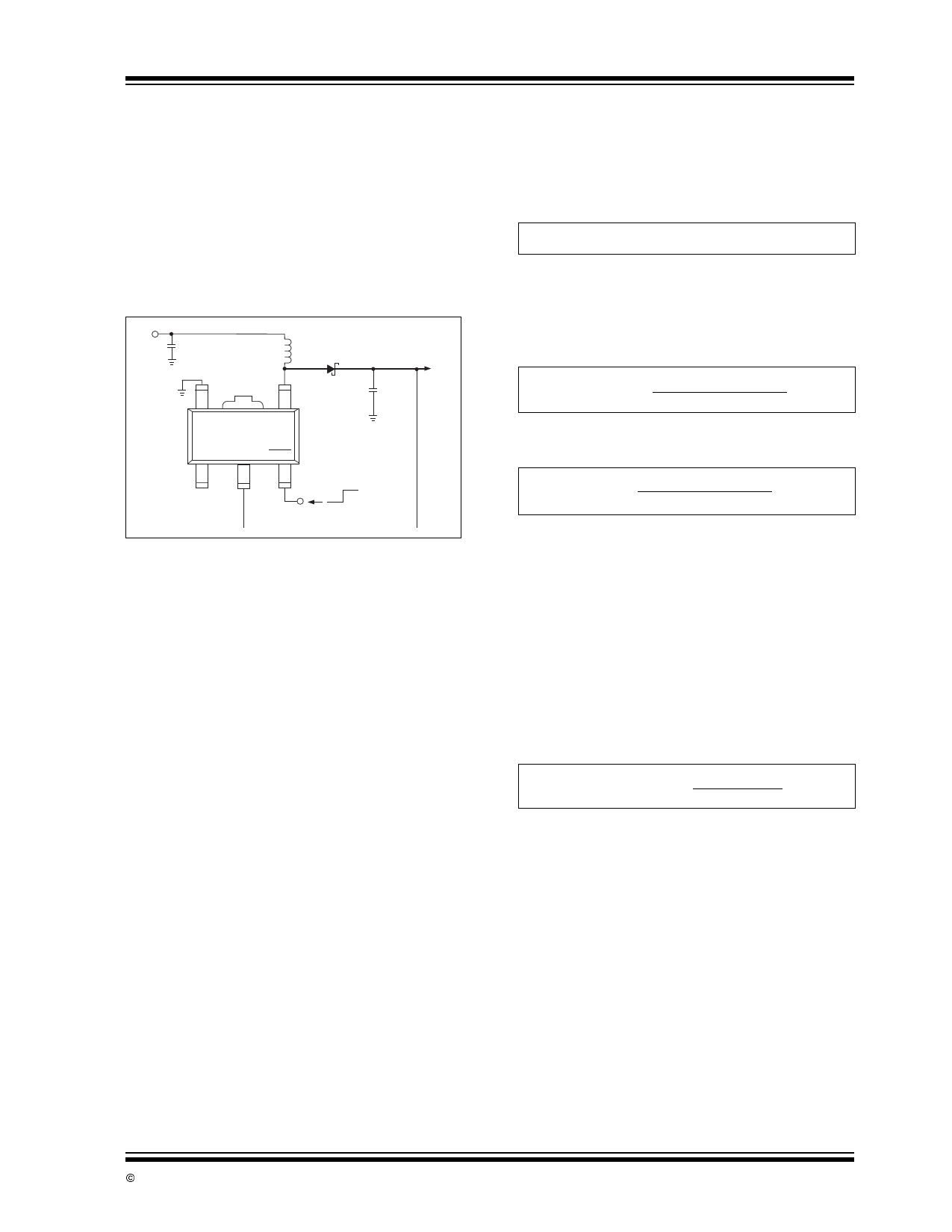
FIGURE 4-1:
TC115 TYPICAL
APPLICATION
VIN
+
C1
L1
D1
+
C2
5
4
GND
LX
TC115
NC
PS
SHDN
1
2
3
VOUT
OFF ON
(Tie to VIN or VOUT
if not used)
4.2 Inductor Selection
Selecting the proper inductor value is a trade-off
between physical size and power conversion require-
ments. Lower value inductors cost less, but result in
higher ripple current and core losses. They are also
more prone to saturate since the coil current ramps to
a higher value. Larger inductor values reduce both
ripple current and core losses, but are larger in physical
size and tend to increase the start-up time slightly.
Practical inductor values, therefore, range from 50µH
to 300µH. Inductors with a ferrite core (or equivalent)
are recommended. For highest efficiency, use an
inductor with a series resistance less than 20 mΩ).
TC115
The inductor value directly affects the output ripple
voltage. Equation 4-3 is derived as shown below, and
can be used to calculate an inductor value, given the
required output ripple voltage (VRIPPLE) and output
capacitor series resistance:
EQUATION 4-1:
VRIPPLE ≈ ESR(di)
where ESR is the equivalent series resistance of the
output filter capacitor, and VRIPPLE is in volts.
Expressing di in terms of switch ON resistance and
time:
EQUATION 4-2:
VRIPPLE ≈
ESR [(VIN – VSW)tON]
L
Solving for L:
EQUATION 4-3:
L ≈ ESR [(VIN – VSW)tON]
VRIPPLE
Care must be taken to ensure the inductor can handle
peak switching currents, which can be several times
load currents. Exceeding rated peak current will result
in core saturation and loss of inductance. The inductor
should be selected to withstand currents greater than
IPK (Equation 4-10) without saturating.
Calculating the peak inductor current is straightforward.
Inductor current consists of an AC (sawtooth) current
centered on an average DC current (i.e., input current).
Equation 4-6 calculates the average DC current. Note
that minimum input voltage and maximum load current
values should be used:
EQUATION 4-4:
Output Power
Input Power = Efficiency
© 2002 Microchip Technology Inc.
DS21361B-page 5
Share Link: 