TC1275 データシートの表示(PDF) - Microchip Technology
部品番号
コンポーネント説明
メーカー
TC1275 Datasheet PDF : 13 Pages
| |||
TC1275/TC1276/TC1277
1.0 ELECTRICAL
CHARACTERISTICS
Absolute Maximum Ratings*
Supply Voltage (VCC to GND) .............................+6.0V
RESET, RESET.......................... -0.3V to (VCC + 0.3V)
Input Current, VCC...............................................20mA
Output Current, RESET, RESET .........................20mA
Power Dissipation (TA ≤ 70°C)
3-Pin SOT-23B (derate 4mW/°C above +70°C)
................................................................. 230mW
Operating Temperature Range............. -40°C to +85°C
Storage Temperature Range .............. -65°C to +150°C
*Stresses above those listed under "Absolute Maximum
Ratings" may cause permanent damage to the device. These
are stress ratings only and functional operation of the device
at these or any other conditions above those indicated in the
operation sections of the specifications is not implied.
Exposure to Absolute Maximum Rating conditions for
extended periods may affect device reliability.
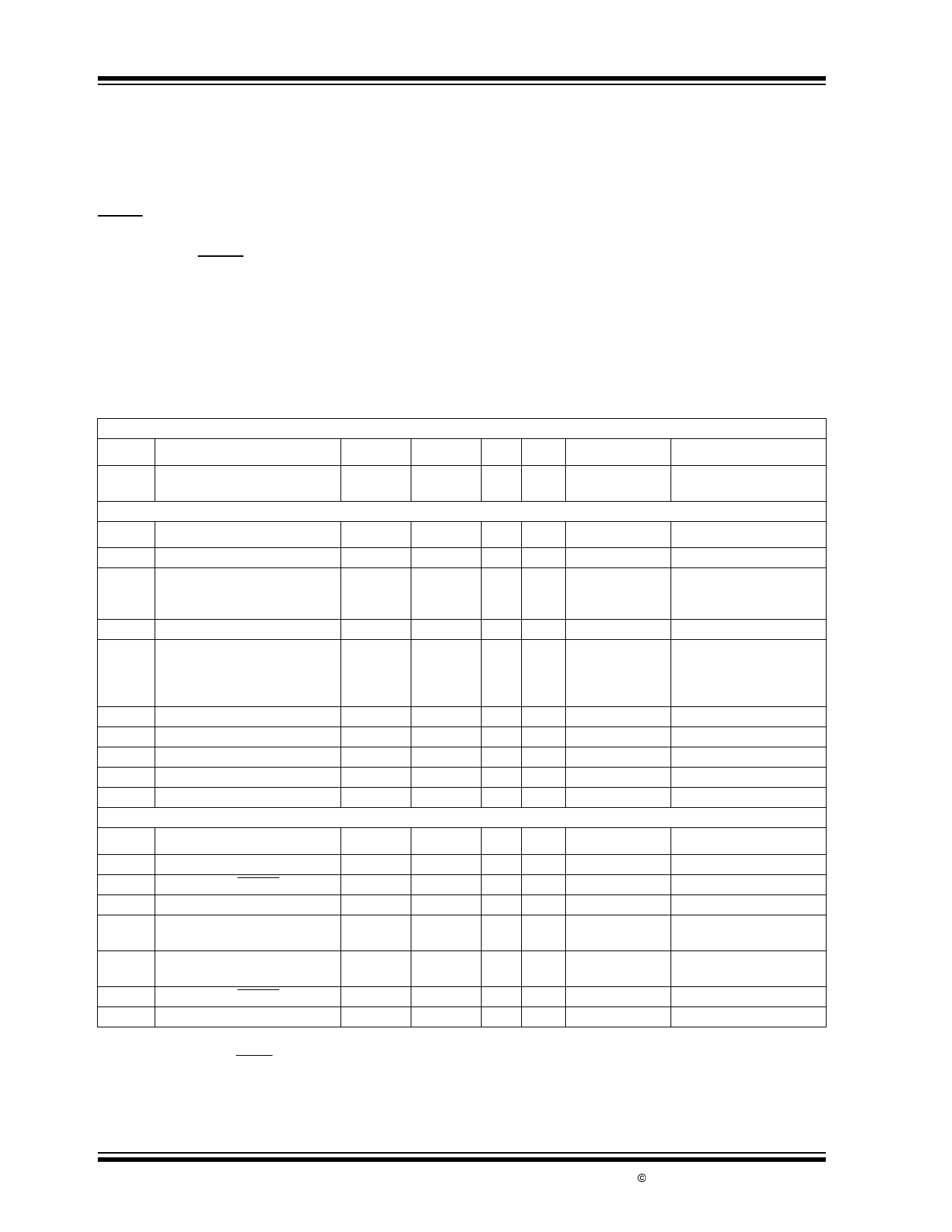
TC1275/TC1276/TC1277 ELECTRICAL SPECIFICATIONS
Recommended DC Operating Conditions: TA = -40°C to +85°C unless otherwise noted. Typical values are at TA = +25°C.
Symbol
Parameter
Min
Typ
Max Units
Device
Test Conditions
VCC
Supply Voltage
1.2
—
5.5 V TC1275, TC1276 Note 1
1.8
—
5.5
TC1277
DC Electrical Characteristics: TA = -40°C to +85°C unless otherwise noted. Typical values are at TA = +25°C.
Symbol
Parameter
Min
Typ
Max Units
Test Conditions
VOH
Output Voltage @ 0-500µA
VCC – 0.5V VCC – 0.1V —
V TC1275, TC1277 Note 1
IOH
Output Current @ 2.4 Volts
VCC = 5V
VCC = 2.7V
mA
—
13
—
TC1275
—
1.3
—
TC1277
Note 2
IOL
Output Current @ 0.4 Volts
+10
30
— mA
Note 2, Note 5
ICC
Operating Current
VCC < 5.5V
VCCTP < VCC < 5.5V
VCC < VCCTP
µA
—
20
35
TC1275, TC1277 Note 3
—
20
35
TC1276
Note 3
—
350
700
TC1276
Note 3
VCCTP-5 VCC Trip Point (TC1275/6/7-5)
2.98
3.06 3.15 V
Note 1
VCCTP-10 VCC Trip Point (TC1275/6/7-10)
2.80
2.88 2.97 V
Note 1
VCCTP-20 VCC Trip Point (TC1275/6/7-20)
2.47
2.55 2.64 V
Note 1
COUT Output Capacitance
—
9
— pF
RP
Internal Pull-Up Resistor
3.0
6.0
9.0 kΩ TC1276
AC Electrical Characteristics: TA = -40°C to +85°C unless otherwise noted. Typical values are at TA = +25°C.
Symbol
Parameter
Min
Typ
Max Units
Test Conditions
tRST
RESET Active Time
100
200
300 msec
tRPD1 VCC Detect to RESET
—
20
50 µsec TC1275, TC1276 VCC(LOW) = 1V, Figure 3-2
tRPD2 VCC Detect to RESET
—
20
50 µsec TC1277
VCC(LOW) = 1V, Figure 3-4
tF
VCC Slew Rate
300
(VCCTP(MAX) to VCCTP(MIN))
—
— µsec
Figure 3-2, Figure 3-4
tR
VCC Slew Rate
0
(VCCTP(MIN) to VCCTP(MAX))
—
— nsec
Figure 3-1, Figure 3-3
tRPU1 VCC Detect to RESET
100
200
300 msec TC1275, TC1276 Note 4, Figure 3-1
tRPU2 VCC Detect to RESET
100
200
300 msec TC1277
Note 4, Figure 3-3
Note 1: All voltages referenced to ground.
2: Measured with VCC ≥ 2.7 volts.
3: Measured with RESET output open for TC1275/TC1276; measured with RESET output open for TC1277.
4: tR = 5µsec.
5: A 1kΩ external resistor may be required in some applications for proper operation of the microprocessor reset control circuit when using
the TC1276.
DS21383B-page 2
© 2002 Microchip Technology Inc.
Share Link: 