TD352I データシートの表示(PDF) - STMicroelectronics
部品番号
コンポーネント説明
メーカー
TD352I Datasheet PDF : 13 Pages
| |||
TD352
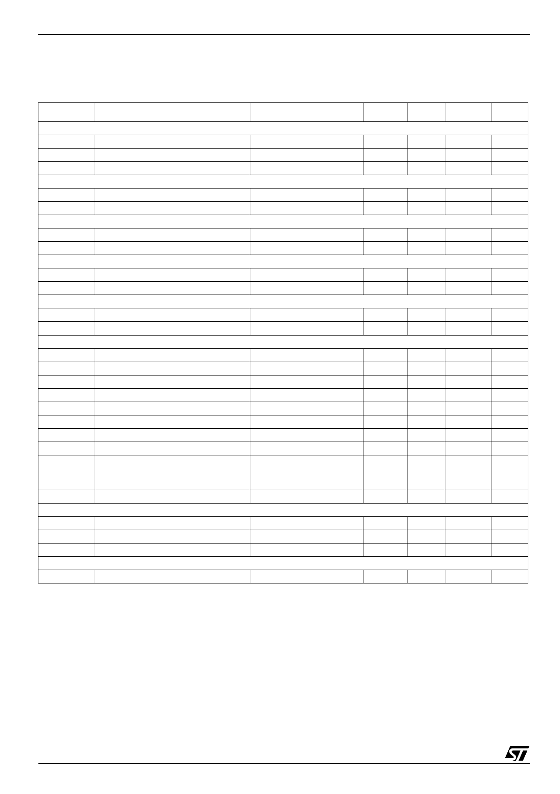
Electrical Characteristics
3 Electrical Characteristics
Table 4. Tamb = -20 to 125°C, VH=16V (unless otherwise specified)
Symbol
Parameter
Input
Vton IN turn-on threshold voltage
Vtoff IN turn-off threshold voltage
Iinp IN Input current
Voltage reference - Note 1
Vref Voltage reference
Iref
Maximum output current
Clamp
Vtclamp CLAMP pin voltage threshold
VCL Clamp low voltage
Delay
Vtdel Voltage threshold
Rdel Discharge resistor
Desaturation protection
Vdes Desaturation threshold
Ides Source current
Outputs
Isink Output sink current
Isrc Output source current
VOL1 Output low voltage 1
VOL2 Output low voltage 2
VOH1 Output high voltage 1
VOH2 Output high voltage 2
tr
Rise time
tf
Fall time
tdon Turn on propagation delay
tdoff Turn off propagation delay
Under Voltage Lockout (UVLO)
UVLOH UVLO top threshold
UVLOL UVLO bottom threshold
Vhyst UVLO hysteresis
Supply current
Iin
Quiescent current
Test Condition
Min
Typ
Max Unit
IN input voltage < 4.5V
0.8
1.0
V
4.0
4.2
V
1
µA
T=25°C
4.85
5.00
5.15
V
10
mA
Icsink=500mA
2.0
V
2.5
V
I=1mA
2.5
V
500
Ω
VH-2
ς
250
µA
Vout=6V
Vout=VH-6V
Iosink=20mA
Iosink=500mA
Iosource=20mA
Iosource=500mA
CL=1nF, 10% to 90%
CL=1nF, 90% to 10%
10% output change:
Rd=4.7k, no Cd
Rd=11k, Cd=220pF
10% output change
1000 1700
mA
750 1300
mA
0.35
V
2.5
V
VH-2.5
V
VH-4.0
V
100
ns
100
ns
500
ns
1.8
2.0
2.2
µs
400
ns
10
11
12
V
9
10
11
V
Vhyst=UVLOH-UVLOL
0.5
1
V
input low, no load
2.5
mA
Note:1.Recommended capacitor range on VREF pin is 10nF to 100nF
4/13
Share Link: 