TDA3857 データシートの表示(PDF) - Philips Electronics
部品番号
コンポーネント説明
メーカー
TDA3857 Datasheet PDF : 14 Pages
| |||
Philips Semiconductors
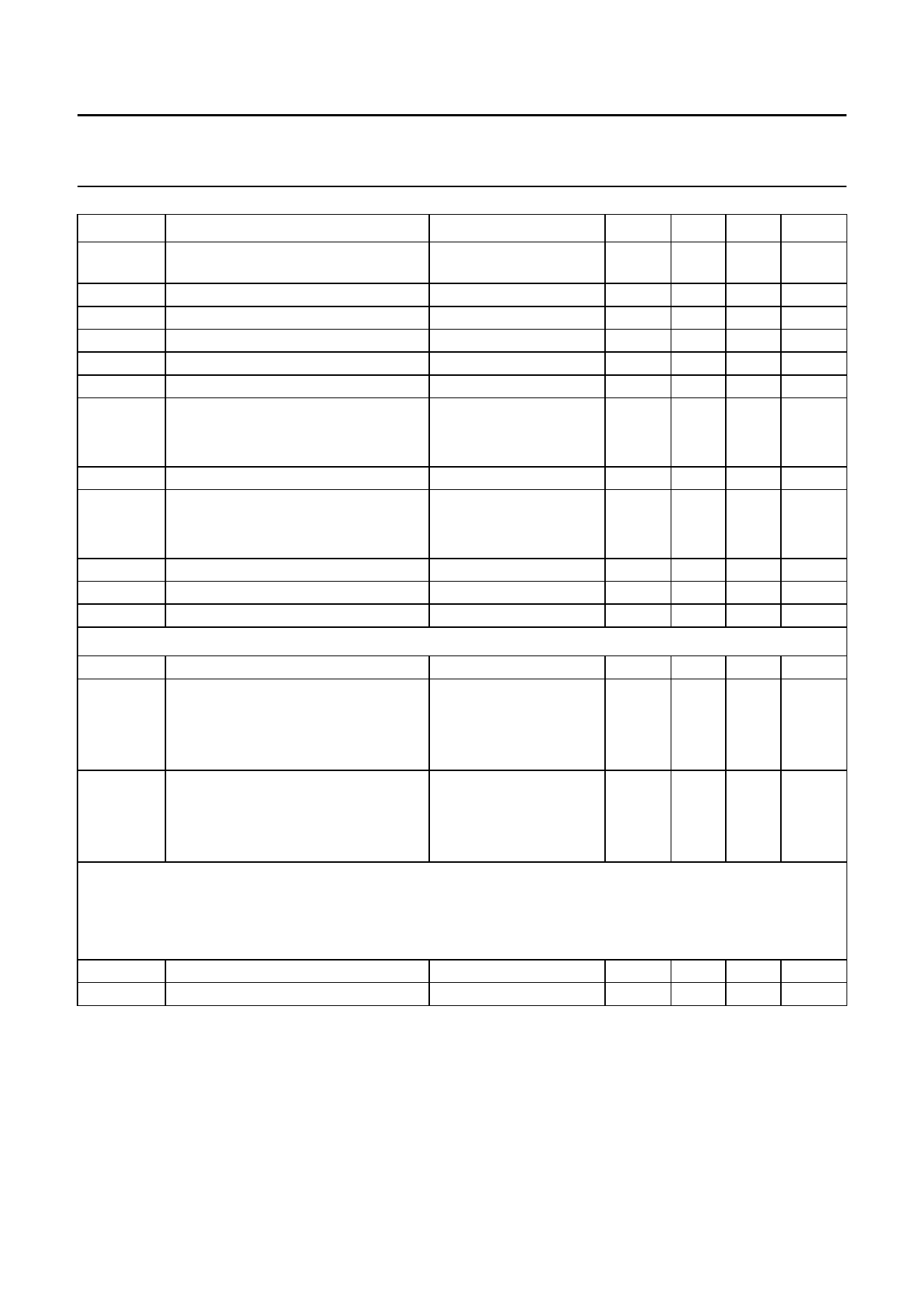
Quasi-split sound processor with two FM demodulators
Product specification
TDA3857
SYMBOL
PARAMETER
CONDITIONS
MIN. TYP.
I6, 7 (M)
I6, 7
THD
Vo (RMS)
αAM
S/N(W)
B
αCR
V3
∆GAF2min
∆GAF2max
V14, 16
allowed AC current of emitter output
(peak value)
maximum allowed DC output current
total harmonic distortion
AF output signal (RMS value)
AM suppression
weighted signal-to-noise ratio
AF bandwidth (−3 dB)
lower limit
upper limit
crosstalk attenuation (pins 6-7)
adjustment voltage for AF2
gain for minimum Vout
gain for maximum Vout
DC voltage (pins 14 and 16)
note 3
THD = 1.5%
1 kHz; m = 0.3
CCIR468-3
note 4
minimum output signal
maximum output signal
V3 = 0 V
V3 = 5 V
−
−
−
1.25
48
64
−
100
60
−
−
−1.5
1.0
−
−
−
0.5
−
54
68
−
−
70
0
5
−2.5
1.5
1.8
Tracking Automatic Frequency Control (AFC) of the vision carrier reference circuit
Vo 12
FTR
S
tracking output voltage (pin 12)
tracking reducing factor for
black picture
white test picture
50% grey picture
AFC steepness (open loop) for
black picture
white test picture
50% grey picture
note 5
VP − 3.3 −
−
9
−
4
−
6
−
−8
−
−3
−
−5.5
AF signal switches
input signals: FM intercarrier into pin 13
no signal in pin 17 (AF2)
see part FM demodulator
the output signals are related to the signals described in the demodulator part.
Vo/Vomute
dV6
AF2 mute attenuation (pin 6)
DC jump at the AF2 output
switching to Mute
70
−
−
5
MAX. UNIT
±1.5 mA
−2
mA
1.0 %
−
V
−
dB
−
dB
20
Hz
−
kHz
−
dB
−
V
−
V
−
dB
−
dB
−
V
VP − 1 V
−
−
−
−
mV/kHz
−
mV/kHz
−
mV/kHz
−
dB
25
mV
June 1994
8
Share Link: 