TDA8011 データシートの表示(PDF) - Philips Electronics
部品番号
コンポーネント説明
メーカー
TDA8011 Datasheet PDF : 12 Pages
| |||
Philips Semiconductors
IF amplifier for satellite TV receivers
Product specification
TDA8011T
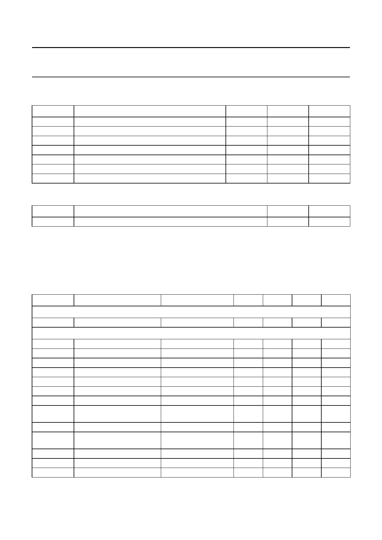
LIMITING VALUES
In accordance with the Absolute Maximum Rating System (IEC 134).
SYMBOL
PARAMETER
VCC
V(max)
Isource(max)
tsc(max)
Tstg
Tj
Tamb
supply voltage
maximum voltage on all pins
maximum output source current
maximum short-circuit time on outputs
storage temperature
junction temperature
operating ambient temperature
MIN.
−0.3
−0.3
−
−
−55
−
−10
MAX.
6.0
VCC
10
10
+150
+150
+80
UNIT
V
V
mA
s
°C
°C
°C
THERMAL CHARACTERISTICS
SYMBOL
Rth j-a
PARAMETER
thermal resistance from junction to ambient in free air
VALUE
160
UNIT
K/W
HANDLING
Inputs and outputs are protected against electrostatic discharge in normal handling. However, to be totally safe it is
desirable to take normal precautions appropriate to handling MOS devices.
CHARACTERISTICS
VCC = 5 V; fi = 70, 480 and 610 MHz; Tamb = 25 °C; measured in application circuit of Fig.6; unless otherwise specified.
SYMBOL
PARAMETER
CONDITIONS
MIN.
TYP.
MAX. UNIT
Supply
ICC
IF amplifier
Gv(max)
Gv(min)
∆G
Vi
VI(DC)
Vo
VO(DC)
F
F(min)
IM3
Ri(diff)
Ci(diff)
Ro(SE)
supply current
27
maximum voltage gain
minimum voltage gain
tilt
VAGC = 0.9VCC; note 1 25
VAGC = 0.1VCC; note 1 −
∆fi = 20 MHz; note 2
−
input voltage level
−
DC input voltage level
−
output voltage level
−
DC output voltage level
−
noise figure
unmatched configuration; −
note 3
minimum noise figure
note 4
−
third-order intermodulation
note 5
−
distance
differential input resistance note 6
−
differential input capacitance note 6
−
single-ended output resistance
−
35
45
−
−
−
−21
0.4
−
−
96
2.5
−
−
85
2.2
−
−
15
−
11
40
−
4
−
0.75
−
50
−
mA
dB
dB
dB
dBµV
V
dBµV
V
dB
dB
dB
kΩ
pF
Ω
February 1995
4
Share Link: 