TEA1552 データシートの表示(PDF) - Philips Electronics
部品番号
コンポーネント説明
メーカー
TEA1552 Datasheet PDF : 24 Pages
| |||
Philips Semiconductors
GreenChip™II SMPS control IC
Product specification
TEA1552
Operation only recommences when the VCC voltage drops
below a level of approximately 4.5 V (practically when the
Vmains has been disconnected for a short period).
The output voltage (VOVP) at which the OVP function trips,
can be set by the demagnetization resistor RDEM:
VOVP = N---N--a---su---x × [IOVP(DEM) × RDEM + Vclamp(DEM)(pos)]
where Ns is the number of secondary turns and Naux is the
number of auxiliary turns of the transformer.
Current IOVP(DEM) is internally trimmed.
The value of the demagnetization resistor (RDEM) can be
adjusted to the turns ratio of the transformer, thus making
an accurate OVP possible.
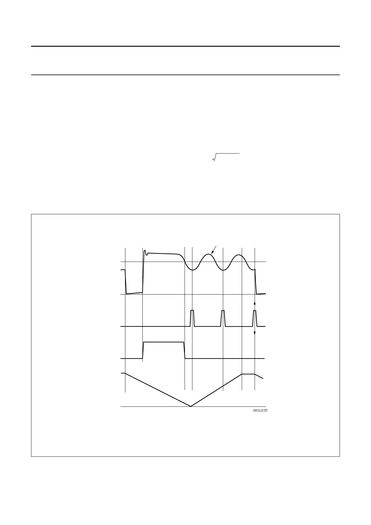
Valley switching (see Fig.8)
A new cycle starts when the power switch is switched on.
After the ‘on-time’ (which is determined by the ‘sense’
voltage and the internal control voltage), the switch is
opened and the secondary stroke starts.
After the secondary stroke, the drain voltage shows an
oscillation with a frequency of approximately
-------------------------1--------------------------
(2 × π × (Lp × Cd))
where Lp is the primary self inductance of the transformer
and Cd is the capacitance on the drain node.
handbook, full pagewidth
primary
stroke
secondary
stroke
drain
secondary
ringing
valley
secondary
stroke
oscillator
B
A
A: Start of new cycle at lowest drain voltage.
B: Start of new cycle in a classical PWM system at high drain voltage.
Fig.8 Signals for valley switching.
MGU235
2002 Aug 27
8
Share Link: 