TK11850 データシートの表示(PDF) - Toko America Inc
部品番号
コンポーネント説明
メーカー
TK11850 Datasheet PDF : 14 Pages
| |||
TK11850L
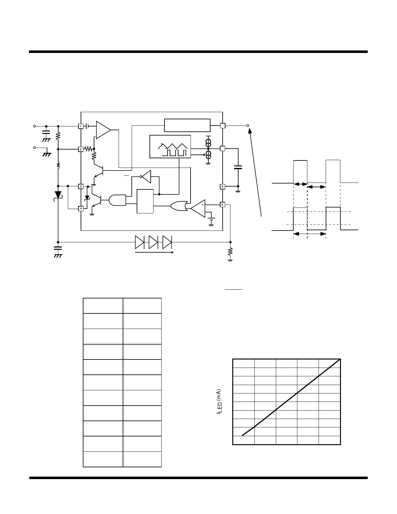
DIMMING (CONT)
2. PWM Dimming
Apply the PWM signal to the EN Terminal (Pin no. 8). In this case, a signal frequency of approximately120 Hz is adequate.
The average current of the LED changes due to the On/Off cycle of the IC, which follows the duty cycle of the PWM signal.
Set the PWM signal at a high level over 2 V and a low level under 0.6 V, with a driving current over 2 mA.
VIN
CIN
GND
RSC
VIN 0.1 V
IS COMP
+
-
IS
L
EXT
CLK
BAND GAP REFERENCE
OSC
0.86 V
Cx 0.3 V
CLK
CLK
EN
8
ON/OFF
CX
7
CX
GND
LED CURRENT CURVE vs. PWM SIGNAL CURVE
LED SETTING
CURRENT
LED CURRENT
D
VOUT
S
Q
R
ERROR
COMP
VFB
VREF
0.525 V
Ton Toff
PWM SIGNAL
(Applied to On/Off pin.)
2.0 V
0.6 V
COUT
fdim = 1 / T = 120 Hz
Duty (%) = (Ton * 100) / T
T
VLED
ILED
(LED CURRENT)
RLED
The PWM dimming LED current follows the PWM signal. (As shown above)
The average LED current is obtained from the formula below. The graph below shows an example with ILED(MAX) (20 mA) at
a Duty Cycle up to 100%.
ILED vs. DUTY
I
=I
* Duty
LED(AVG)
LED(MAX) 100
DUTY (%)
ILED (mA)
100
20.0
90
18.0
80
16.0
70
14.0
60
12.0
50
10.0
40
8.0
30
6.0
20
4.0
10
2.0
LED CURRENT (ILED) vs.
DUTY CYCLE OF INPUT PWM SIGNAL
20
18
16
14
12
10
8
6
4
2
0
0
20
40
60
80
100
DUTY CYCLE (%)
May 2001 TOKO, Inc.
Page 11
Share Link: 