TK14584 データシートの表示(PDF) - Toko America Inc
部品番号
コンポーネント説明
メーカー
TK14584 Datasheet PDF : 20 Pages
| |||
TK14584
CIRCUIT DESCRIPTION (CONT.)
The signal from the phase shifter is applied to the multiplier (in the dotted line) through emitter-follower stage QA. When
the phase shifter is connected between Pin 10 and Pin 9, note that the bias voltage to Pin 9 should be provided from an
external source because Pin 9 is only connected to the base of QA.
Because the base of QB (at the opposite side) is connected with the supply voltage, Pin 9 has to be biased with the
equivalent voltage.
Using an LC resonance circuit is not a problem (see Figure 5). However, when using a ceramic discriminator, it is necessary
to pay attention to bias. If there is a difference of the base voltages, the DC voltages of the multiplier do not balance. It
alters the DC zero point or worsens the distortion of demodulation output.
The Pin 9 input level should be saturated at the multiplier; if this level is lower, it is easy to disperse the modulation output.
Therefore, to have stable operation, Pin 9 should be higher than 100 mVP-P.
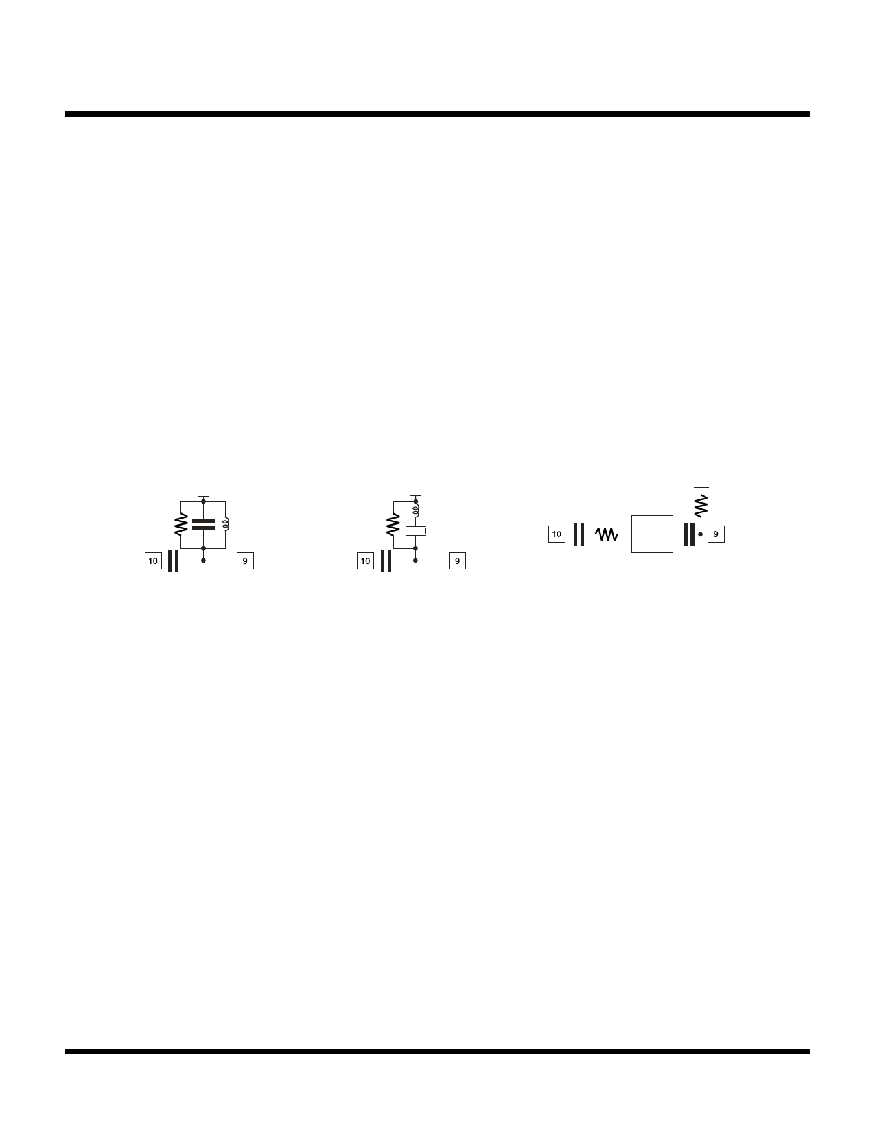
The following figures show examples of the phase shifter.
Rz is the characteristic impedance
VCC
VCC
VCC
Rz
Rz
Delay
Line
LC resonance circuit
ceramic discriminator
delay line
FIGURE 5 - EXAMPLES OF PHASE SHIFTERS
Establishing Demodulation Characteristics:
Generally, demodulation characteristics of FM detectors are determined by the external phase shifter. However, this
product has a unique function which can optionally establish the demodulation characteristics by the time constant of the
circuit parts after demodulation. The following explains this concept.
Figure 6 shows the internal equivalent circuit of the detector output stage.
The multiplier output current of the detector is converted to a voltage by the internal OP AMP. The characteristic of this
stage is determined by converting the current to voltage with resistor R and the capacitor C connected between Pin 7
O
O
and Pin 8 (see Figure 6).
In other words, the slope of the S-curve characteristic can be established optionally with resistor RO without changing the
constant of the phase shifter. The demodulated bandwidth can be established optionally by the time constant of this
external resistor RO and capacitor CO inside of a bandwidth of the IF-filter and phase shifter. Figure 7 shows an example
of this characteristic.
Page 16
January 2000 TOKO, Inc.
Share Link: 