TK14584 データシートの表示(PDF) - Toko America Inc
部品番号
コンポーネント説明
メーカー
TK14584 Datasheet PDF : 20 Pages
| |||
TK14584
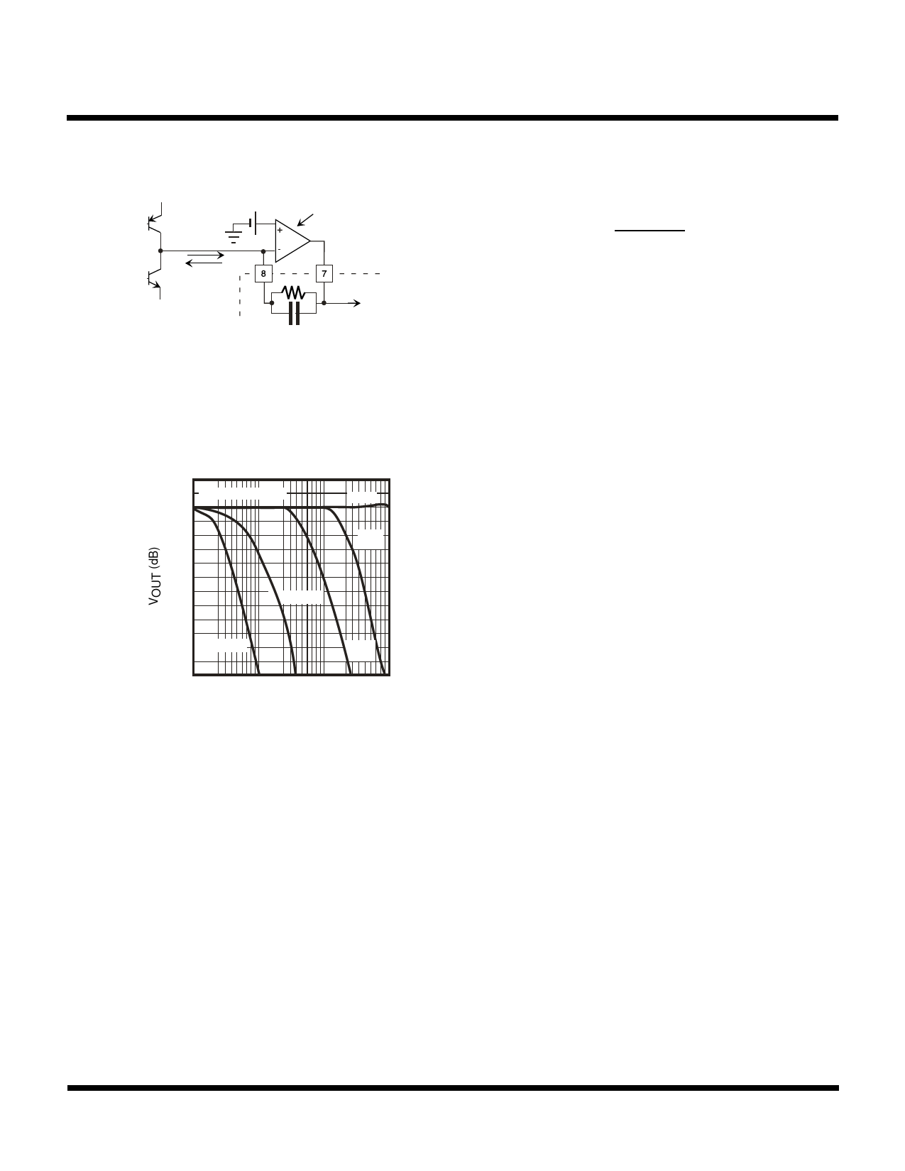
CIRCUIT DESCRIPTION (CONT.)
Vref
io
Demodulated
Output Current
I to V convertor
R0
Demodulated
Output Voltage
VOUT
C0
The -3 dB frequency Fc is calculated by the following:
Fc = 1
2 π C0R0
The S-curve output voltage is calculated by the following
as centering around the internal reference voltage Vref:
V
OUT
=
V
ref
±
io
X
R
0
Where Vref = 1.4 V, maximum of current io = ±100 µA
FIGURE 6 - INTERNAL EQUIVALENT CIRCUIT OF DETECTOR OUTPUT STAGE
2
0 dB = 35.2 mVrms
0
-2
-4
-6
C = 330 pF
-8
C=∞
C=
10 pF
-10 C = 1000 pF
C=
47 pF
-12
1 3 10 30 100 300 1000
MODULATING FREQUENCY fm (Hz)
Operating Condition:
Measured by the standard test circuit.
Parallel resistor to phase shift coil = 1 kΩ.
fIN = 10.7 MHz, modulation = ±100 kHz.
External capacitance CO = 0~1000 pF.
FIGURE 7 - EXAMPLE: BANDWIDTH OF DEMODULATION VS. TIME CONSTANT CHARACTERISTIC
Center Voltage of Detector DC Output:
The center voltage of the detector DC output is determined by the internal reference voltage source. It is impossible to
change this internal reference voltage source, but it is possible to change the center voltage by the following method.
As illustrated in Figure 8, the demodulated output current at Pin 8 is converted to the voltage by an external resistor R1
without using the internal OP AMP.
Figure 9 shows an example of a simple circuit that divides the supply voltage into halves using resistors. Since both circuits
have a high output impedance, an external buffer amplifier should be connected.
January 2000 TOKO, Inc.
Page 17
Share Link: 